1. Determine the maximum deflection d in a simply supported beam of length L carrying a uniformly distributed load of intensity w, applied over its entire length. 2. For the beam loaded as shown in the Figure, compute the moment of area of the M diagrams between the reactions about both the left and the right reaction. (Hint: Draw the moment diagram by parts from right to left). 500 N 1 m 2 m 1 m 400 N/m R1
1. Determine the maximum deflection d in a simply supported beam of length L carrying a uniformly distributed load of intensity w, applied over its entire length. 2. For the beam loaded as shown in the Figure, compute the moment of area of the M diagrams between the reactions about both the left and the right reaction. (Hint: Draw the moment diagram by parts from right to left). 500 N 1 m 2 m 1 m 400 N/m R1

Mechanics of Materials (MindTap Course List)
9th Edition
ISBN:9781337093347
Author:Barry J. Goodno, James M. Gere
Publisher:Barry J. Goodno, James M. Gere
Chapter10: Statically Indeterminate Beams
Section: Chapter Questions
Problem 10.4.38P: A fixed-end beam AB of a length L is subjected to a uniform load of intensity q acting over the...

Related questions

Question
Transcribed Image Text:Home Work:
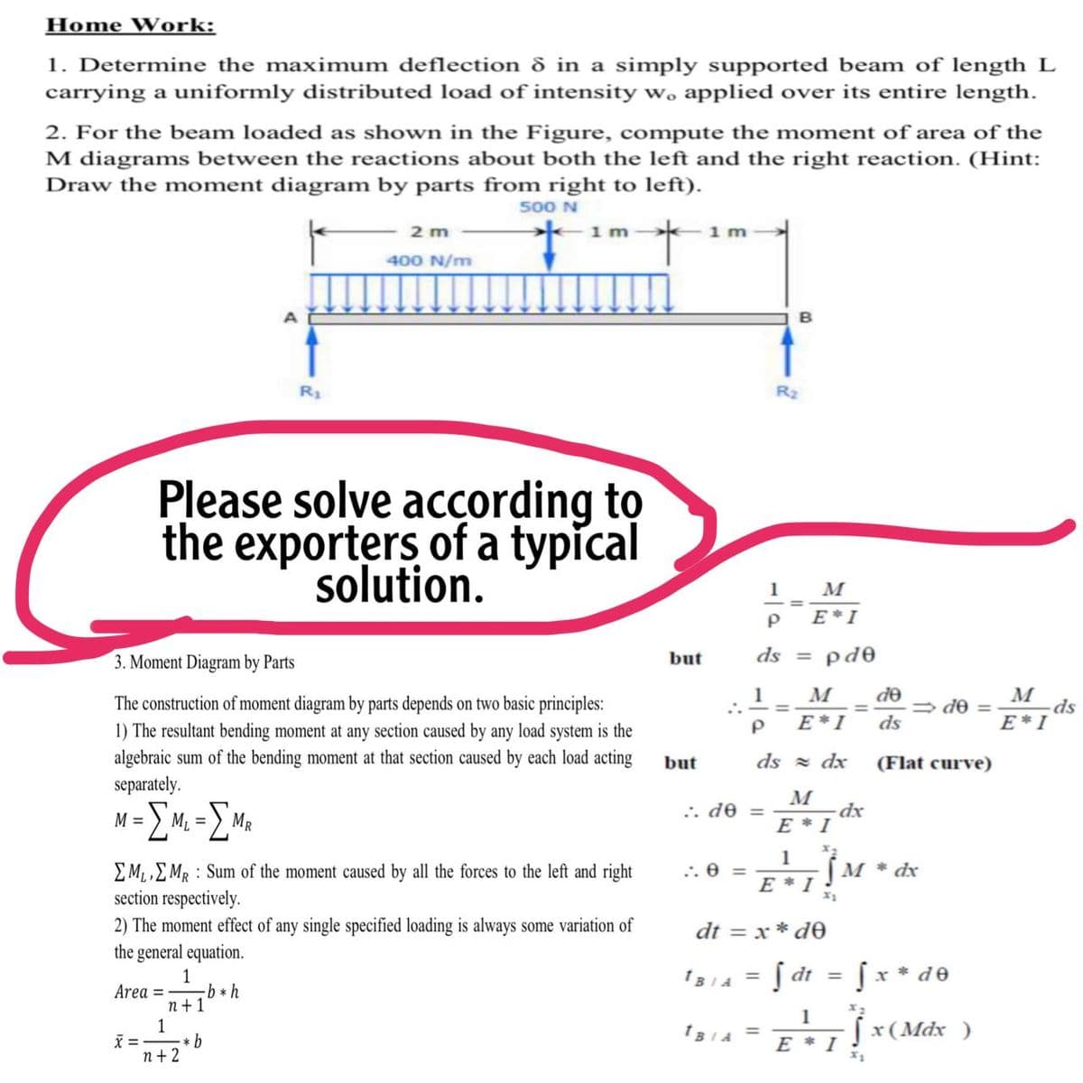
1. Determine the maximum deflection d in a simply supported beam of length L
carrying a uniformly distributed load of intensity w, applied over its entire length.
2. For the beam loaded as shown in the Figure, compute the moment of area of the
M diagrams between the reactions about both the left and the right reaction. (Hint:
Draw the moment diagram by parts from right to left).
500 N
2 m
1 m
1 m
400 N/m
R1
R2
Please solve according to
the exporters of a typical
solution.
1
E*I
3. Moment Diagram by Parts
but
ds = pd0
M
de
M
ds
E*I
1
The construction of moment diagram by parts depends on two basic principles:
1) The resultant bending moment at any section caused by any load system is the
= de =
%3D
E*I
ds
algebraic sum of the bending moment at that section caused by each load acting
separately.
but
ds = dx
(Flat curve)
M
=) M2 =
Σ
= OP **
E * I
MR
1
[M * dx
EM,EMR : Sum of the moment caused by all the forces to the left and right
section respectively.
:. 0 =
E * I
2) The moment effect of any single specified loading is always some variation of
the general equation.
dt = x * de
Į dt
x * de
1
Area = b * h
n+1
1
IBIA =
1
[x(Mdx )
X = -
* b
1BIA =
E * I
n + 2
Expert Solution
This question has been solved!
Explore an expertly crafted, step-by-step solution for a thorough understanding of key concepts.

Step by step
Solved in 2 steps with 2 images

Knowledge Booster


Learn more about
Need a deep-dive on the concept behind this application? Look no further. Learn more about this topic, mechanical-engineering and related others by exploring similar questions and additional content below.Recommended textbooks for you
Mechanics of Materials (MindTap Course List)
Mechanical Engineering
ISBN:
9781337093347
Author:
Barry J. Goodno, James M. Gere
Publisher:
Cengage Learning
Mechanics of Materials (MindTap Course List)
Mechanical Engineering
ISBN:
9781337093347
Author:
Barry J. Goodno, James M. Gere
Publisher:
Cengage Learning