1. Determine the maximum positive bending moment in the beam in kN-m. 2. Determine the maximum shear in kN. 3. Determine the location of Neutral Axis, in mm, from the top of the section. 4. Determine the location of the centroid, in mm, from the left of the section. 5. Determine the moment of inertia of the section in x106 mm4 . 6. Determine the moment capacity of the section, kN-m, if fbcap≤300 MPa. 7. Determine the maximum flexural stress experienced by the beam in
1. Determine the maximum positive bending moment in the beam in kN-m. 2. Determine the maximum shear in kN. 3. Determine the location of Neutral Axis, in mm, from the top of the section. 4. Determine the location of the centroid, in mm, from the left of the section. 5. Determine the moment of inertia of the section in x106 mm4 . 6. Determine the moment capacity of the section, kN-m, if fbcap≤300 MPa. 7. Determine the maximum flexural stress experienced by the beam in

Mechanics of Materials (MindTap Course List)
9th Edition
ISBN:9781337093347
Author:Barry J. Goodno, James M. Gere
Publisher:Barry J. Goodno, James M. Gere
Chapter5: Stresses In Beams (basic Topics)
Section: Chapter Questions
Problem 5.11.12P: Two W 310 × 74 Steel wide-flange beams are bolted together to form a built-up beam as shown in the...

Related questions

Question
1. Determine the maximum positive bending moment in the beam in kN-m.
2. Determine the maximum shear in kN.
3. Determine the location of Neutral Axis, in mm, from the top of the section.
4. Determine the location of the centroid, in mm, from the left of the section.
5. Determine the moment of inertia of the section in x106 mm4 .
6. Determine the moment capacity of the section, kN-m, if fbcap≤300 MPa.
7. Determine the maximum flexural stress experienced by the beam in MPa.
8. Determine the maximum shearing stress in MPa at Neutral Axis.
9. Determine the spacing of rivets in mm.
10. Determine the maximum flexural stress at 1 m from the support at D to E in MPa.
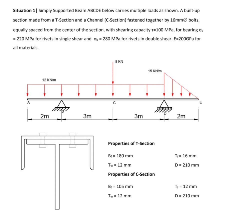
Transcribed Image Text:Situation 1| Simply Supported Beam ABCDE below carries multiple loads as shown. A built-up
section made from a T-Section and a Channel (C-Section) fastened together by 16mmØ bolts,
equally spaced from the center of the section, with shearing capacity t=100 MPa, for bearing ơb
= 220 MPa for rivets in single shear and ob = 280 MPa for rivets in double shear. E=200GPA for
all materials.
8 KN
15 KN/m
12 KN/m
A
E
2m
3m
3m
2m
Properties of T-Section
Bf = 180 mm
Tf= 16 mm
Tw = 12 mm
D = 210 mm
Properties of C-Section
Bf = 105 mm
Tf = 12 mm
Tw = 12 mm
D = 210 mm
Expert Solution
This question has been solved!
Explore an expertly crafted, step-by-step solution for a thorough understanding of key concepts.

Step by step
Solved in 6 steps with 8 images

Knowledge Booster


Learn more about
Need a deep-dive on the concept behind this application? Look no further. Learn more about this topic, mechanical-engineering and related others by exploring similar questions and additional content below.Recommended textbooks for you
Mechanics of Materials (MindTap Course List)
Mechanical Engineering
ISBN:
9781337093347
Author:
Barry J. Goodno, James M. Gere
Publisher:
Cengage Learning
Mechanics of Materials (MindTap Course List)
Mechanical Engineering
ISBN:
9781337093347
Author:
Barry J. Goodno, James M. Gere
Publisher:
Cengage Learning