1. In Digital, open the "4-bit subtractor" circuit (RCS4.dig) 2. You should see inputs and outputs similar to the 4-bit RCA. 3. Create something similar to your 4-bit RCA circuit (see image below) but now, pass each bit of the subtrahend (operand B) through the logic gat that flips it. (You already know which logic gate - you answered the question earlier!) 4. Rotate the gate so that it faces SOUTH. 5. Make sure to set the correct carry-in bit to the correct value! It should look something like this: O Cin Full Adder Full Adder Full Adder Cout SUM Cout SUM Cout SUM Cout SUM Cout Does your subtractor circuit work? Try to input A= -5 and B = -3 as operands. Be mindful of which bits correspond to A3A2A1A0 and B3B2B1Bo! What answer did you get? Input your answer in bits, and remember to consider only S3S2S,So, i.e. discard Cout. Answer: O A3 ɛa O O B2 O A1 18 O O AO 09 O
1. In Digital, open the "4-bit subtractor" circuit (RCS4.dig) 2. You should see inputs and outputs similar to the 4-bit RCA. 3. Create something similar to your 4-bit RCA circuit (see image below) but now, pass each bit of the subtrahend (operand B) through the logic gat that flips it. (You already know which logic gate - you answered the question earlier!) 4. Rotate the gate so that it faces SOUTH. 5. Make sure to set the correct carry-in bit to the correct value! It should look something like this: O Cin Full Adder Full Adder Full Adder Cout SUM Cout SUM Cout SUM Cout SUM Cout Does your subtractor circuit work? Try to input A= -5 and B = -3 as operands. Be mindful of which bits correspond to A3A2A1A0 and B3B2B1Bo! What answer did you get? Input your answer in bits, and remember to consider only S3S2S,So, i.e. discard Cout. Answer: O A3 ɛa O O B2 O A1 18 O O AO 09 O

Chapter22: Sequence Control
Section: Chapter Questions
Problem 6SQ: Draw a symbol for a solid-state logic element AND.

Related questions

Question
Topic: Logic Gates
1000 is not the answer. its wrong
1010 is not the answer too. its wrong
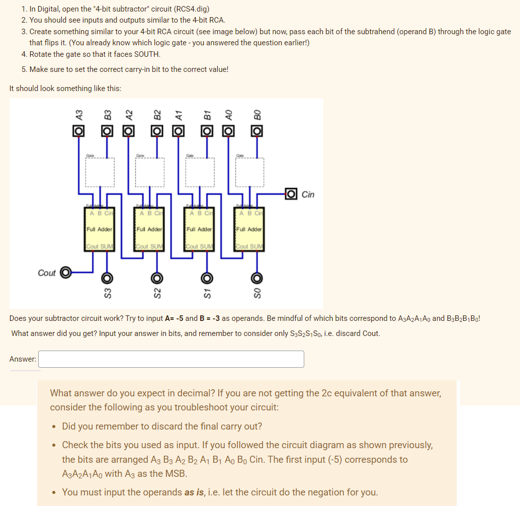
Transcribed Image Text:1. In Digital, open the "4-bit subtractor" circuit (RCS4.dig)
2. You should see inputs and outputs similar to the 4-bit RCA.
3. Create something similar to your 4-bit RCA circuit (see image below) but now, pass each bit of the subtrahend (operand B) through the logic gate
that flips it. (You already know which logic gate - you answered the question earlier!)
4. Rotate the gate so that it faces SOUTH.
5. Make sure to set the correct carry-in bit to the correct value!
It should look something like this:
O Cin
AB Cir
AB Cin
B Cin
B Cin
Full Adder
Full Adder
Full Adder
Full Adder
Cout SUM
Cout SUM
Cout SUM
Cout SUM
Cout
Does your subtractor circuit work? Try to input A= -5 and B = -3 as operands. Be mindful of which bits correspond to A3A2A1A0 and B3B2B1Bo!
What answer did you get? Input your answer in bits, and remember to consider only S3S2S1S0, i.e. discard Cout.
Answer:
What answer do you expect in decimal? If you are not getting the 2c equivalent of that answer,
consider the following as you troubleshoot your circuit:
• Did you remember to discard the final carry out?
Check the bits you used as input. If you followed the circuit diagram as shown previously,
the bits are arranged A3 B3 A2 B2 A1 B1 Ao Bo Cin. The first input (-5) corresponds to
A3A2A¡Ao with Ag as the MSB.
• You must input the operands as is, i.e. let the circuit do the negation for you.
08 O
Ov O
18 O
O A1
za O
S1
O A2
Expert Solution
This question has been solved!
Explore an expertly crafted, step-by-step solution for a thorough understanding of key concepts.

Step by step
Solved in 2 steps with 1 images

Knowledge Booster


Learn more about
Need a deep-dive on the concept behind this application? Look no further. Learn more about this topic, electrical-engineering and related others by exploring similar questions and additional content below.Recommended textbooks for you