1. In the figure shown, determine the stress in the cable C if its area is 600 mm². Neglect the weight of the bar AB. 2. In Problem 1, determine the required diameter of the pin at A if the allowable stress is 80 MPa. (double shear).
1. In the figure shown, determine the stress in the cable C if its area is 600 mm². Neglect the weight of the bar AB. 2. In Problem 1, determine the required diameter of the pin at A if the allowable stress is 80 MPa. (double shear).

Mechanics of Materials (MindTap Course List)
9th Edition
ISBN:9781337093347
Author:Barry J. Goodno, James M. Gere
Publisher:Barry J. Goodno, James M. Gere
Chapter2: Axially Loaded Members
Section: Chapter Questions
Problem 2.8.9P

Related questions
Question
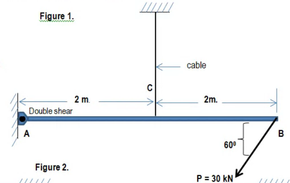
Transcribed Image Text:Figure 1.
cable
C
2 m.
2m.
Double shear
A
B
60°
Figure 2.
P = 30 kN
Transcribed Image Text:1. In the figure shown, determine the stress in the
cable C if its area is 600 mm?. Neglect the weight
of the bar AB.
2. In Problem 1, determine the required diameter of
the pin at A if the allowable stress is 80 MPa.
(double shear).
Expert Solution
This question has been solved!
Explore an expertly crafted, step-by-step solution for a thorough understanding of key concepts.

Step by step
Solved in 2 steps with 2 images

Recommended textbooks for you
Mechanics of Materials (MindTap Course List)
Mechanical Engineering
ISBN:
9781337093347
Author:
Barry J. Goodno, James M. Gere
Publisher:
Cengage Learning
Mechanics of Materials (MindTap Course List)
Mechanical Engineering
ISBN:
9781337093347
Author:
Barry J. Goodno, James M. Gere
Publisher:
Cengage Learning