1. This question relates to stresses due to combined loading. A shaft subjected to combined torsion and axial thrust is designed to resist a shear stress and a compressive stress as shown in Figure Q1. Using the information provided in Table Q1: Figure Q1 Txy 90 mpa 10x 130 mpa
1. This question relates to stresses due to combined loading. A shaft subjected to combined torsion and axial thrust is designed to resist a shear stress and a compressive stress as shown in Figure Q1. Using the information provided in Table Q1: Figure Q1 Txy 90 mpa 10x 130 mpa

Mechanics of Materials (MindTap Course List)
9th Edition
ISBN:9781337093347
Author:Barry J. Goodno, James M. Gere
Publisher:Barry J. Goodno, James M. Gere
Chapter7: Analysis Of Stress And Strain
Section: Chapter Questions
Problem 7.3.16P: A propeller shaft subjected to combined torsion and axial thrust is designed to resist a shear...

Related questions

Question
Transcribed Image Text:1.
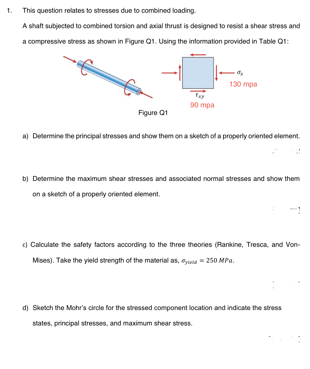
This question relates to stresses due to combined loading.
A shaft subjected to combined torsion and axial thrust is designed to resist a shear stress and
a compressive stress as shown in Figure Q1. Using the information provided in Table Q1:
Figure Q1
Txy
90 mpa
ox
130 mpa
a) Determine the principal stresses and show them on a sketch of a properly oriented element.
b) Determine the maximum shear stresses and associated normal stresses and show them
on a sketch of a properly oriented element.
c) Calculate the safety factors according to the three theories (Rankine, Tresca, and Von-
Mises). Take the yield strength of the material as, Oyield = 250 MPa.
d) Sketch the Mohr's circle for the stressed component location and indicate the stress
states, principal stresses, and maximum shear stress.
Expert Solution
This question has been solved!
Explore an expertly crafted, step-by-step solution for a thorough understanding of key concepts.

Step by step
Solved in 4 steps with 2 images

Knowledge Booster


Learn more about
Need a deep-dive on the concept behind this application? Look no further. Learn more about this topic, mechanical-engineering and related others by exploring similar questions and additional content below.Recommended textbooks for you
Mechanics of Materials (MindTap Course List)
Mechanical Engineering
ISBN:
9781337093347
Author:
Barry J. Goodno, James M. Gere
Publisher:
Cengage Learning
Mechanics of Materials (MindTap Course List)
Mechanical Engineering
ISBN:
9781337093347
Author:
Barry J. Goodno, James M. Gere
Publisher:
Cengage Learning