1. Waveform Tracing: Construct the waveform of the following flip-flops. a.) High-Level Clocking D Flip-flop (Qin = 1) CLK PRE CLR D Q
Q: Here are some impu responses n[n] ne and continuous -time LTI systems, where u[n] and u(t) are the…
A: An LTI system stands for a Linear Time-Invariant system. It is a mathematical model used to describe…
Q: V₁ =12V R1 m 33052 R2 47052 R3 2202
A:
Q: 5. Solve (hint: combine series or parallel resistors, and combine series voltage sources and…
A:
Q: 5V(+ Μ 16Ω Μ ΚΩ Μ 16Ω Μ RL = ΙΚΩ
A:
Q: Determine the voltages Va, Vb, and Vab for the networks in Fig. 5.125.
A: In the given questions we need to calculate the node voltage.
Q: Calculate the current in mA from Is and IR1 to IR4
A: In this question, we need to determine the current Is and in each resistances. We solve this problem…
Q: Find the unknown quantities for the networks in Fig. 6.93 using the information provided. Dr. Saif…
A:
Q: The following voltage waveform is applied to a 10 S2 resistor. Develop a program to plot voltage,…
A: Given a plot,To plot the voltage, current, power, and energy as a function of time, you can use the…
Q: 9. Derive the transfer function of the electrical circuit shown below. Draw a schematic diagram of…
A:
Q: 10.58 The impedance Z₁ in the circuit in Fig. P10.58 is ad- justed for maximum average power…
A: The impedance Z₁ in the circuit is ad- justed for maximum average power transfer to ZL The internal…
Q: .→ If-the-voltage-and-current-of-a-single-phase-load-are-1.1772-4°-and-21 -8° A, find.the. reactive…
A:
Q: Question A-iii: The angle between the vector field F at point P and the vector T=3 aR + 2 a, -1 a…
A: Given vector field is, and point for and .
Q: ind the Voltages of all four nodes in the diagram for the following questions.(USE NODAL ANALYSIS)…
A: Nodal analysis, also known as node-voltage analysis, is a method used to analyze electrical circuits…
Q: In the circuit shown in the figure (Figure 1) both batteries have insignificant internal resistance…
A:
Q: 3- Derive equation [VNBFM = Accoswet + BAc/2[cos(wc + Wm) + cos(wc - Wm)]
A: Unfortunately, I cannot derive the given equation without any context or information about the…
Q: Using Kirchhoff's voltage law, find the unknown voltages for the configurations in Fig. 5.107.
A: In the given question we need to calculate the unknown voltage using the kirchoff rule
Q: -5 The integration 10 cos(4nt +) (t-1)dt O 1. 40 O 2. 40pi O 3. -10 O 4. 20pi O 5. None of the…
A: To solve the following integration:
Q: 2. Determine the current through R2 in terms of the given circuit parameters. R2 R V1 V 11 4 R1 R Đ…
A:
Q: In Double circuit, a total of six conductors are provided to make two different Transmission…
A: Given Statement:In double circuit, a total of six conductors are provided to make two different…
Q: Use the information in Fig. 6.80 to calculate: a. The source voltage E. b. The resistance R2. c. The…
A: In the given circuit the value of the voltage, resistor R2 and the current I1 needs to be…
Q: (c) Using Boolean algebra, (i) Simplify Y.Y (ii) Simplify Y.Y + 1.Y+Z+X.Z (iii) Prove that X-Z + X Y…
A:
Q: Calculate the values of Voltages, Currents, and Resistances in the following Series- Parallel…
A: In the given DC circuit, we need to determine voltage and current for each element.
Q: I have an ESP-WROOM-32D board, a RCWL-0516 Microwave Radar Proximity Sensor, a blue LED, and a green…
A: if I have an ESP-WROOM-32D board, a RCWL-0516 Microwave Radar Proximity Sensor, a blue LED, and a…
Q: Calculate the node voltages from Va to Vd
A: The given circuit is shown below.
Q: nd current of a three – phase load are as follows: Voltage: 3.6 kV, 8 degrees Current: 37 A, 45…
A: We are given voltage and current of a three-phase load as follows:V=3.6 kV, 8 degrees,Current = 37…
Q: Using the voltage divider rule or Kirchhoff's voltage law, determine the unknown voltages for the…
A: In the given questions we need to calculate the unknown voltage.
Q: Calculate the equivalent resistance of the circuit in the Figure below, where R₁ = 209, R₂ = 15 Q2,…
A: In the given circuit the value of the equivalent resistance needs to be calculated and the same can…
Q: For each of the following cases, find the complex power, the average power and the reactive power.
A: For each of the following cases, find the complex power, the average power and the reactive power.…
Q: a. Write the mesh equations for the network of Fig. 8.121 using the format approach to mesh…
A:
Q: Q.4 (a) Briefly explain the following DC motors: - (i) Separately excited DC Motor (ii) Permanent…
A: Since you have posted the multiple questions with multiple support. So we are supposed to answer 1st…
Q: Given the following Boolean function, F = AB + A'C + BC Derive a truth table of the above…
A: Given the following Boolean function,F = AB + A'C + BC derive a truth table of the above…
Q: Find the Q-point for the circuit in the following figure. For βF = 40 and 250 using the numerical…
A:
Q: Given 1 Y₁ [n] = 2N+1 Σ x[n-k] k=-N a) Get the impulse response b) If h₁ [2] = 1 2N + 1 2N + 1 2 sin…
A: The input-output relationship of filter 1 is given as:(a) We need to determine its impulse…
Q: Problem 5 A 3-phase abc-sequenced balanced source drives two loads: A-connected with Z₁ = 20+ j15 •…
A: In this question, we need to determine the complex power of the loads.we know, complex power in…
Q: 4.26 In a certain region of space, the charge density is given in cylindrical coordinates by the…
A: Given that, the charge density function in cylindrical coordinate system is, .The objective is to…
Q: 5V(+ Μ UYI >1ΚΩ Μ ΙΚΩ VL Μ •1ΚΩ Μ
A: Nodal analysis uses ohms law and Kirchhoffs current law.The detailed solution is provided below.
Q: t-2-8n t-6-8n. The signal x (t) = Σm=- [4 (228)- A(-2₂8)] has: Σ=[Δ Δ( O 1. Has imaginary Fourier…
A: Given:a signal, we need to find fourier series coefficient of the signal and select the correct…
Q: x[n] = ,η > 0 (3) (0, otherwise where W n=0 an 1–α 21: ηπα 1 = b – a + 1 1
A: An energy signal has finite energy over a finite period of time.Energy signals have zero power…
Q: Iыз- Ibc-Iab = 156,-43 2-153.7° - 156.43/-33.7° О 270.9 L 176.3 A How ?
A: Here we have to clarify the calculations given.
Q: 20 mA 20mA io (20-10) + 0 Σ5 ΚΩ Vo 2 ΚΩ W Using KVL, KCL, and Ohm law only (Direct Method Only) (Do…
A: In this question, we need to determine the voltage Vo, current io and power delivered by the voltage…
Q: 11 11 22m A R1 68052 R2 R3 33302 54705.
A:
Q: Using Passive Sign Convention, plot P2v(t) the power for the 2V source across the following time…
A: Given:we are required to find and plot the power for the 2 V source for the range of
Q: Is क्य R डॉट हेरि 24 12 टिप -m डेटिड
A: Given Data:A DC resistive circuit with,Supply current To Find:The current
Q: 1. Your TA will select 6 resistors (R₁ to R6) from the standard resistor values in Table 1 between…
A: According to the question, for the given electric circuit as shown belowR1 = 1.2k, R2 = 3.0k, R3 =…
Q: Find V, in the circuit in Fig. 4 60,00 ΦΩ 1:2 8 Ω Μ Τ Figure .4 ΖΩ 8 Ω
A:
Q: Complete the truth table for a three-input AND gate: (replace the question marks with a number) ABC…
A: The given logic gate is,Given truth table is,Asked to find the output of the truth table?
Q: For the network in Fig. below: a. Determine voltages Va, Vb, and Vc. b. Find voltages Vac and Vbc.…
A:
Q: If a load of R3 = 400 is connected to the terminals a--b, what will the value of Vab [Select]…
A: Resistance can refer to opposition to something, like resistance to change or resistance to…
Q: 1. Determine the inverse of the Fourier transform -az F (w) 0 62 00 @-
A: Since you have posted multiple questions, we will provide the solution only to the first question as…
Q: A resistor made out of gold (conductivity = 4.1.107 ) has a cross section with area A = 2mm² and…
A:
simple answer the waveform thanks
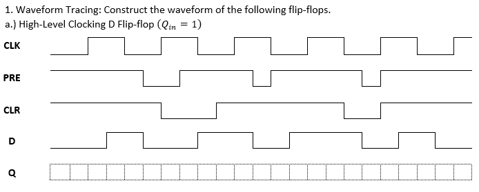
Step by step
Solved in 3 steps with 2 images
how about if it's low level clocking d flip flop?? what is the waveform for it?
- Determine the Q waveform for the flip-flop as seen in the figure below. Assume that Q = 0 initially.Design an Implementation of 8-bit Floating Light Digital Circuit Implementation Using D Flip-Flop. Interpret the results. (Hint: Using Shift Register)Design a modulus seven synchronous counter that can count 0, 3, 5, 7, 9, 11, and 12 using D flip-flop.
- Use T flip flops to design a counter with the repeated binary sequence: 0,1,3,5,7. The circuit is to be designed by treating the unused states as don’t care conditions. Sketch the state diagram Derive the state table Implement the circuit.A binary pulse counter can be constructed byinterconnecting T-type flip-flops in an appropriatemanner. Assume it is desired to construct a counterwhich can count up to 10010. a. How many flip-flops would be required?b. Sketch the circuit needed to implement this counter.Kindly design a Master-slave J-K flip-flop using NAND gates only and staterace-around condition, and how it can be eliminated in a Master-slave J-K flipflop? A multiplexer (MUX) also known as data selector, is a logic circuit which allowsthe digital information from multi-inputs to a single output line
- Design the asynchronous counter circuit using JK flip-flops, starting from the smallest decimal digit to the largest decimal digit in the following numbers. (1180501624)a) Kindly design a Master-slave J-K flip-flop using NAND gates only and state race-around condition, and how it can be eliminated in a Master-slave J-K flipflop? A multiplexer (MUX) also known as data selector, is a logic circuit which allows the digital information from multi-inputs to a single output line(b) Design a 8 to 1 multiplexer by using the four variable function given by F (A, B, C, D) = ∑m = (013489 15) (c) OUR school AIT has lockers in all the campus that she often rent them out to students who needs them, upon graduation they are taken back by the school authorities. Kindly express the process of opening this locker in terms of digital operation.Design a counter that has the following repeated binary sequence: 1, 3, 5, 7 using T-flip flops.
- Design the circuit that can count from 0 ,14,6, using the suitable Flip-Flop, showing the following steps: Excitation table State table k-maps circuit diagram/designd) Write down the transition table for T flip flop.e) Suppose, you want to design a 4-bit down counter which only counts the odd numbers.Write down the state table for the counter.Design a Mode 14 asynchronous forward counter circuit. (Use JK or T type flip-flops) I designed the mode 11 forward counter circuit below (using JK or T type flip-flop) Can you draw a Mod 14 asynchronous forward counter circuit as in the photo?