10 k2 1V 100 k2 90 k2 10 k2 50 k2 Find the vo and i, for the given circuit. (Op-Amp is ideal vo = 3.4 and i, = 0.45 A B vo = 2.7 and i, = 0.45 %3D C vo = 3.4 and i, = 0.28 %3D vo = 2.7 and io = 0.28 D E Inappropriate feedback design ww
10 k2 1V 100 k2 90 k2 10 k2 50 k2 Find the vo and i, for the given circuit. (Op-Amp is ideal vo = 3.4 and i, = 0.45 A B vo = 2.7 and i, = 0.45 %3D C vo = 3.4 and i, = 0.28 %3D vo = 2.7 and io = 0.28 D E Inappropriate feedback design ww

Power System Analysis and Design (MindTap Course List)
6th Edition
ISBN:9781305632134
Author:J. Duncan Glover, Thomas Overbye, Mulukutla S. Sarma
Publisher:J. Duncan Glover, Thomas Overbye, Mulukutla S. Sarma
Chapter12: Power System Controls
Section: Chapter Questions
Problem 12.3P

Related questions
Question
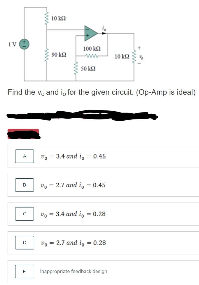
Transcribed Image Text:10 k2
1 V
100 k2
90 k2
10 k2
50 k2
Find the vo and i, for the given circuit. (Op-Amp is ideal)
A
v, = 3.4 and i, = 0.45
v, = 2.7 and i, = 0.45
v, = 3.4 and i, = 0.28
vo = 2.7 and io = 0.28
E
Inappropriate feedback design
ww
Expert Solution
This question has been solved!
Explore an expertly crafted, step-by-step solution for a thorough understanding of key concepts.

Step by step
Solved in 2 steps with 1 images

Knowledge Booster


Learn more about
Need a deep-dive on the concept behind this application? Look no further. Learn more about this topic, electrical-engineering and related others by exploring similar questions and additional content below.Recommended textbooks for you
Power System Analysis and Design (MindTap Course …
Electrical Engineering
ISBN:
9781305632134
Author:
J. Duncan Glover, Thomas Overbye, Mulukutla S. Sarma
Publisher:
Cengage Learning
Power System Analysis and Design (MindTap Course …
Electrical Engineering
ISBN:
9781305632134
Author:
J. Duncan Glover, Thomas Overbye, Mulukutla S. Sarma
Publisher:
Cengage Learning