1012 112 100 V Figure 4.20 System diagram for Problem 4.2a 1 2 10 2 100 V Figure 4.21 System diagram for Problem 4.2b 4.3 (a) Referring to Figure 4.20, set an instantaneous relay at bus A. Calculate the pickup for faults on buses A and B and discuss the application of the instantaneous relay for this configuration. (b) Repeat (a) for Figure 4.21 4.4 Repeat Problems 4.2 and 4.3 for a system where the two segments are both equal to 4.5 (a) Referring to the relay characteristics of Appendix D (a)-(c), determine the oper- ating time for each relay with a 5.0A pickup, time dial setting of 3, and a fault current of 15.0 A. (b) Which relay, and what time dial setting, should be used if the relay is set at 5.0 A pickup, with a fault current of 15.0 A, and operating time of 1.5 s? (c) Select two different relays, their pickup, and time dial settings when the fault current is 20.0 A and the relay must operate in 2s. 4.6 For the radial system shown in Figure 4.22, calculate the instantaneous and time- delay overcurrent relay settings at each bus. Assume that the transformer must not be de-energized and that the relays at bus B are "looking into" a transformer differential and do not need to coordinate with it. Assume that any pickup tap is available, but use the relay characteristic of Figure 4.5. 2 100 A ctr 30/1 50 A ctr-20/1 Minimum.fault 3000 A Maximum. fault 9000 A 2000 A 5000 A 1000 A 3000 A Figure 4.22 System diagram for Problem 4.6
1012 112 100 V Figure 4.20 System diagram for Problem 4.2a 1 2 10 2 100 V Figure 4.21 System diagram for Problem 4.2b 4.3 (a) Referring to Figure 4.20, set an instantaneous relay at bus A. Calculate the pickup for faults on buses A and B and discuss the application of the instantaneous relay for this configuration. (b) Repeat (a) for Figure 4.21 4.4 Repeat Problems 4.2 and 4.3 for a system where the two segments are both equal to 4.5 (a) Referring to the relay characteristics of Appendix D (a)-(c), determine the oper- ating time for each relay with a 5.0A pickup, time dial setting of 3, and a fault current of 15.0 A. (b) Which relay, and what time dial setting, should be used if the relay is set at 5.0 A pickup, with a fault current of 15.0 A, and operating time of 1.5 s? (c) Select two different relays, their pickup, and time dial settings when the fault current is 20.0 A and the relay must operate in 2s. 4.6 For the radial system shown in Figure 4.22, calculate the instantaneous and time- delay overcurrent relay settings at each bus. Assume that the transformer must not be de-energized and that the relays at bus B are "looking into" a transformer differential and do not need to coordinate with it. Assume that any pickup tap is available, but use the relay characteristic of Figure 4.5. 2 100 A ctr 30/1 50 A ctr-20/1 Minimum.fault 3000 A Maximum. fault 9000 A 2000 A 5000 A 1000 A 3000 A Figure 4.22 System diagram for Problem 4.6

Power System Analysis and Design (MindTap Course List)
6th Edition
ISBN:9781305632134
Author:J. Duncan Glover, Thomas Overbye, Mulukutla S. Sarma
Publisher:J. Duncan Glover, Thomas Overbye, Mulukutla S. Sarma
Chapter14: Power Distribution
Section: Chapter Questions
Problem 14.18P

Related questions
Question
Transcribed Image Text:1012
112
100 V
Figure 4.20 System diagram for Problem 4.2a
1 2
10 2
100 V
Figure 4.21
System diagram for Problem 4.2b
4.3
(a) Referring to Figure 4.20, set an instantaneous relay at bus A. Calculate the pickup
for faults on buses A and B and discuss the application of the instantaneous relay
for this configuration. (b) Repeat (a) for Figure 4.21
4.4 Repeat Problems 4.2 and 4.3 for a system where the two segments are both equal to
4.5
(a) Referring to the relay characteristics of Appendix D (a)-(c), determine the oper-
ating time for each relay with a 5.0A pickup, time dial setting of 3, and a fault
current of 15.0 A. (b) Which relay, and what time dial setting, should be used if the
relay is set at 5.0 A pickup, with a fault current of 15.0 A, and operating time of
1.5 s? (c) Select two different relays, their pickup, and time dial settings when the
fault current is 20.0 A and the relay must operate in 2s.
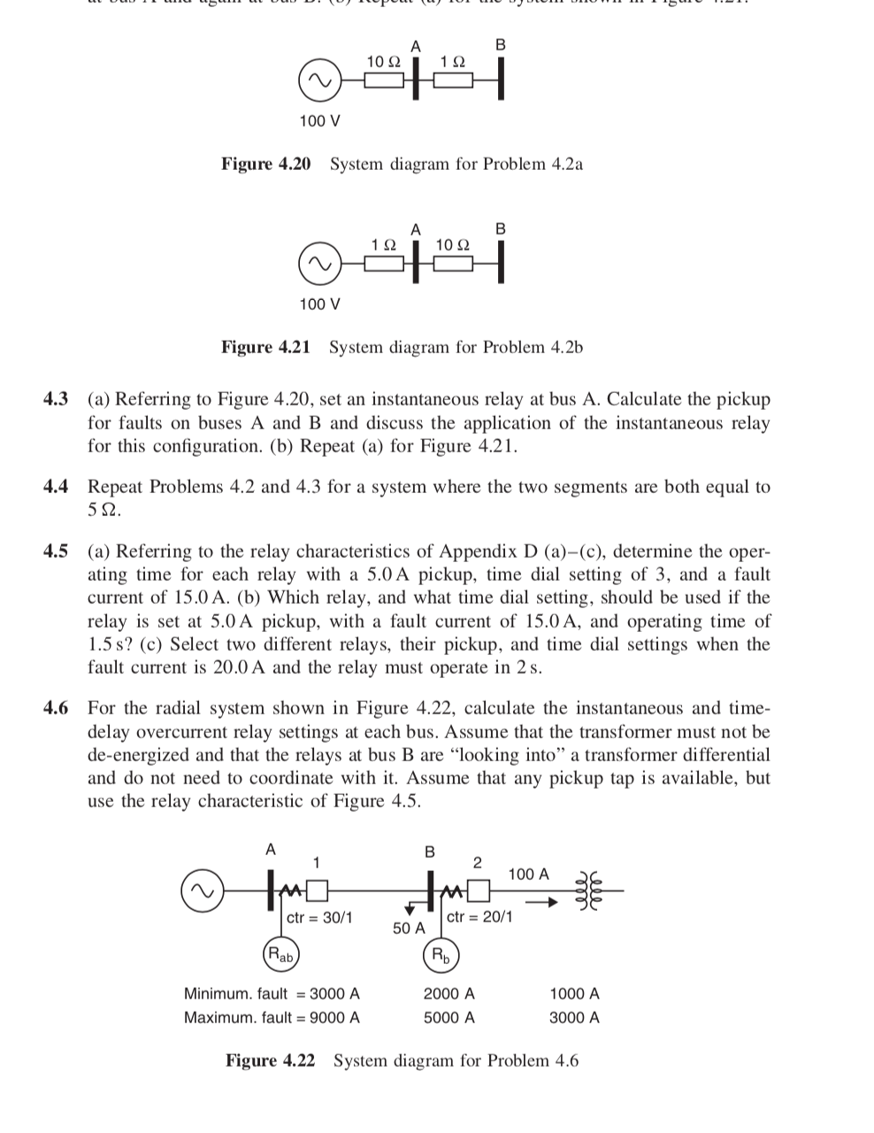
4.6 For the radial system shown in Figure 4.22, calculate the instantaneous and time-
delay overcurrent relay settings at each bus. Assume that the transformer must not be
de-energized and that the relays at bus B are "looking into" a transformer differential
and do not need to coordinate with it. Assume that any pickup tap is available, but
use the relay characteristic of Figure 4.5.
2
100 A
ctr 30/1
50 A ctr-20/1
Minimum.fault 3000 A
Maximum. fault 9000 A
2000 A
5000 A
1000 A
3000 A
Figure 4.22
System diagram for Problem 4.6
Expert Solution
This question has been solved!
Explore an expertly crafted, step-by-step solution for a thorough understanding of key concepts.

This is a popular solution!

Trending now
This is a popular solution!

Step by step
Solved in 4 steps with 4 images

Recommended textbooks for you
Power System Analysis and Design (MindTap Course …
Electrical Engineering
ISBN:
9781305632134
Author:
J. Duncan Glover, Thomas Overbye, Mulukutla S. Sarma
Publisher:
Cengage Learning
Power System Analysis and Design (MindTap Course …
Electrical Engineering
ISBN:
9781305632134
Author:
J. Duncan Glover, Thomas Overbye, Mulukutla S. Sarma
Publisher:
Cengage Learning