11-1. Draw the shear and moment diagrams for the shaft. The bearings at A and Bexert only vertical reactions an the shaft. -N0 mm- 250 mim 24 kN
11-1. Draw the shear and moment diagrams for the shaft. The bearings at A and Bexert only vertical reactions an the shaft. -N0 mm- 250 mim 24 kN

International Edition---engineering Mechanics: Statics, 4th Edition
4th Edition
ISBN:9781305501607
Author:Andrew Pytel And Jaan Kiusalaas
Publisher:Andrew Pytel And Jaan Kiusalaas
Chapter7: Dry Friction
Section: Chapter Questions
Problem 7.30P: Solve Prob. 7.29 if =0.

Related questions
Question
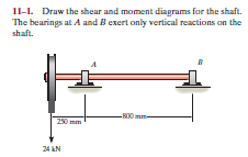
Transcribed Image Text:11-1. Draw the shear and moment diagrams for the shaft.
The bearings at A and Bexert only vertical reactions an the
shaft.
-N0 mm-
250 mim
24 kN
Expert Solution
This question has been solved!
Explore an expertly crafted, step-by-step solution for a thorough understanding of key concepts.

This is a popular solution!

Trending now
This is a popular solution!

Step by step
Solved in 2 steps with 2 images

Recommended textbooks for you
International Edition---engineering Mechanics: St…
Mechanical Engineering
ISBN:
9781305501607
Author:
Andrew Pytel And Jaan Kiusalaas
Publisher:
CENGAGE L
International Edition---engineering Mechanics: St…
Mechanical Engineering
ISBN:
9781305501607
Author:
Andrew Pytel And Jaan Kiusalaas
Publisher:
CENGAGE L