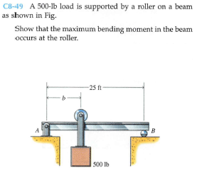
C8-49 A 500-lb load is supported by a roller on a beam as shown in Fig. Show that the maximum bending moment in the beam occurs at the roller. -25 ft- A B 500 lb


Q: Draw the influence lines for the vertical reactions at supports A and E and the reaction moment at…
A: First, make a FBD of the diagram as shown below.
Q: C8-49 A 500-lb load is supported by a roller on a beam as shown in Fig. Plot |Mmax, the maximum…
A: Free-body diagram of beam is given as, On using force equilibrium in vertical direction, On using…
Q: I1-13. Draw the shear and moment diagrams for the beam. м, L/2-
A: Solution : The reaction at the support is calculated as:
Q: The compound beam is fixed at A, pin connected at B, and supported by a roller at C. Draw the shear…
A: Draw the free body diagram. Calculate the reactions: Since the beam is pin jointed at B therefore…
Q: 16-3. A picture is taken of a man performing a pole vault, and the minimum radius of curvature of…
A: Given: The radius of curvature, ρ = 4.5 m The diameter of the pole, d = 40 mm The modulus of…
Q: The shaft shown below is supported by a thrust bearing at A and a journal bearing at B. Draw the…
A:
Q: 150 Ib 110 Ib/ft A B 2 ft. 8 ft By Value of reaction at B Value of X (3dec.places) in segment BC…
A: Consider the Free Body Diagram: Balancing forces in vertical direction:By+Cy=150+110*8By+Cy=1030…
Q: Draw the shear and moment diagram for each problem Use Method of Section (as Solution A) and Method…
A: SFD and BMD
Q: 6.43-6.56 Construct the shear force and bending moment diagrams for the beam shown by the area…
A: According to the details provided in the question, we need to calculate we need to calculate SFD…
Q: *11-16. A reinforced concrete pier is used to support the stringers for a bridge deck. Draw the…
A: Given , Free body diagram of the beam ( bading diagram) Taking moment about point 'A'Rb x…
Q: F6-11. Draw the shear and moment diagrams for the double-overhang beam.
A: As per the guidelines we are subjected to solve only one question at a time please repost this…
Q: Determine the reactions at the journal bearing supports A, B, and C of the shaft, then draw the…
A: Given Weight pulley 1 = 400 N Weight pulley 2 = 400 N Support bearing A, B, C To find Shear force…
Q: The shaft is supported by a smooth thrust bearing at A and smooth journal bearing at B. Draw the…
A: Given , Free body diagram of the shaft loading diagram Consider…
Q: F6-8. Draw the shear and moment diagrams for the cantilever beam. 6 kN 12 kN-m A -1.5 m- -1.5 m-…
A:
Q: The beam is used to support a dead load of 0.6 k/ft, a live load of 2 k/ft and a concentrated live…
A: Given data are, Live load= 2 k/ft Dead load= 0.6 k/ft Generated live load= 8 k Now, draw the FBD of…
Q: P= 16 15 9 15 R2 2 (m) R1 3 (m) 2 (m) 6 (m) The beam is in equilibrium. Find force R2.
A:
Q: F7-18. Draw the shear and moment diagrams for the beam. 9 kN/m А 3 m 3 m F7-18
A:
Q: 11-38. The compound beam is fixed at A, pin connected at B, and supported by a roller at C. Draw the…
A: Draw the free body diagram: Find the reactions: Since the beam is pin jointed at the point B…
Q: 3 kip.ft 3 ft A - 6 ft B
A:
Q: Determine the reaction at the supports, then draw the shear and moment diagrams. EI is constant.
A:
Q: P1: (a) Determine the internal shear force and bending moment in member BCDE immediately to the left…
A: For equilibrium of AC ΣM@A = 0 = Rc x Lac – 600 = 0 Rc = 600/5 = 120lb For equilibrium of BCDE ΣM@E…
Q: The beam is supported by the bolted supports at its ends. When loaded these supports initially do…
A:
Q: I1-14. Draw the shear and moment diagrams for the beam. 30 kN/m 45 kN-m -1.5m- -15 m- -15 m- Prob.…
A: Draw the free body diagram of the beam: Calculate the reactions: Consider moment equilibrium about…
Q: The beam is subjected to the uniform distributed load shown. Draw the shear and moment diagrams for…
A: For the given beam, the point in section AB where shear force changes sign (x2 metres from A) is to…
Q: Determine the reaction at the roller support and draw the bending-moment diagram for the beam and…
A: The free body digram is shown as, Consider only RB and M0 = 0 Deflection due RB will be y1=RBL33EI…
Q: 11-1. Draw the shear and moment diagrams for the shaft. The bearings at A and Bexert only vertical…
A: Given data Load acting on the shaft at the left end, P = 24 kN. Draw the free-body diagram of the…
Q: 6-14. Draw the shear and moment diagrams for the beam. 2 kip/ft 30 kip-ft В A- -5 ft - 5 ft - 5 ft…
A:
Q: The cable will fail when subjected to a tension of 2 kN. Determine the largest vertical load P the…
A: Internal Normal Force, Nc=2 KN → Shear Force, Vc=0.5333 KN ↓ Moment, Mc=0.4 KN.m ↻
Q: The 80-lb weight is dropped from rest at a height h = 4 ft onto the end of the A-36 steel W6 * 12…
A: To find-: The maximum bending stress developed in the beam. Given-: The weight of the body is W=80…
Q: In cach case, draw the shear and moment diagrams for the beam. F6-5. 4 kN/m 4 kN/m +150- 3m F6-5
A: Since the given figure is overhanging beam and symmetrical loading at each end, therefore, the…
Q: 11-25. Draw the shear and moment diagrams for the simply supported beam. 45 kN /m -2 m-
A: Given Data: The triangular load varies from w1= 0 to w2= 45 kN/m over a span of l = 4 m. The…
Q: A man with his tools having a total weight W = 1.012 kN, steps on the retractable ladder. %3D The…
A: Given data, Total weight, W = 1.012 KN h = 540 mm = 0.54 m l1 = 0.365 m l2 = 0.286 m l3 = 0.761 m To…
Q: Draw the shearing-force and bending-moment diagrams for the beam - A cantilever of length 12 m…
A: We have given Draw the shearing-force and bending-moment diagrams for the beam - A cantilever of…
Q: 5.5. Plot the shear and bending-moment diagrams for the beam shown if P = 0, wi = 0, and wz = 10…
A: as per the bartleby guidelines i can answer only question so please the next question again. thank…
Q: The beam is subjected to the uniform distributed load shown. Draw the shear and moment diagrams for…
A:
Q: 7-81. Draw the shear and moment diagrams for the beam. Problem 7-81 6 ft 200 lb/ft 6 ft
A: Draw the free-body diagram of the beam. Apply force equilibrium in horizontal direction. HB=0…
Q: 4.24-4.47 Construct the shear force and bending moment diagrams for the beam shown by the area…
A: Bending moment and shear force digram needs to plot using area method
Q: 6-7. Draw the shear and moment diagrams for the compound heam which is pin connected at 8.(This…
A:
Q: 7-76. Draw the shear and moment diagrams for the beam 15 kN 10 kN/m 20 kN · m А -2 m -1 m 1 m 2 m
A:
Q: *7-48. Draw the shear and moment diagrams for the cantilevered beam. 100 lb 800 lb ft A C В 5 ft 5…
A:
Q: 11-35. A short link at Bis used to conect beams AB and BC to form the compound beam. Draw the shear…
A: Draw the F.B.D of the given beam.
Q: The footing supports the load transmitted by the two columns. Draw the shear and moment diagrams for…
A: The free-body diagram is given as, consider the equilibrium in the y-direction,…
Q: 87.5 V C D (kN) -12.5 -62.5 Identify the loaded beam where this shear diagram is from.
A:
Q: -10 ft 150 k-ft B -10 ft- 60 к Į с -10 ft-
A: To Find : The shear and bending moment diagram. Free Body diagram: The F.B.D diagram is,
Q: 6.21-6.38 For the beam shown, derive the expressions for V and M, and draw the shear force and…
A: For a step-by-step solution have a look through the attached pictures of the solution. The required…
Q: -36. The compound beam is fixed at A, pin connected a B. and supported by a roller at C. Draw the…
A: Given, Point Load P = 2 kN UDL w = 3 kN/m
Q: Draw the shear and moment diagrams for the frame shown. Assume A is a pin, C is a roller, and B is a…
A:
Q: 6-1. Draw the shear and moment diagrams for the shaft. The bearings at A and B exert only vertical…
A: First draw the force diagram of the beam Now apply the equilibrium equation for vertical forces,
Q: Determine the vertical reaction (A y - kN) and the reactive moment (M A - kN·m) at the support at A…
A: To find : The vertical reaction and reactive moment at A. Given that : The Moment is…
Q: *6-12. A reinforced concrete pier is used to support the stringers for a bridge deck. Draw the shear…
A: solved


Trending now
This is a popular solution!

Step by step
Solved in 4 steps with 15 images

- Determine the shear force, V and its bending moment, M. kindly provide the SFD and BMDThe shaft is supported by a smooth thrust bearing at A and smooth journal bearing at C. If d = 3 in., determine the absolute maximum bending stress in the shaft.An A-36 steel strap having a thickness of 10 mm and a width of 20 mm is bent into a circular arc of radius r = 10 m. Determine the maximum bending stress in the strap.
- If the beam in Prob. 6–28 has a rectangular cross section with a width b and a height h, determine the absolute maximum bending stress in the beam.Determine the absolute maximum bending stress in the tubular shaft if di = 160 mm and do = 200 mmThe beam is used to support a dead load of 0.6 k/ft, a live load of 2 k/ft and a concentrated live load of 8 k. Determine (a) the maximum positive (upward) reaction at A, (b) the maximum positive moment at C, and (c) the maximum positive shear just to the right of the support at A. Assume the support at A is a pin and B is a roller.
- A load of 100 kN, followed by another load of 50 kN, at a distance of 10 metres, advances across a girder with a 100-metre span. Obtain an expression for the maximum bending moment at a section of the girder at a distance of z metres from an abutment. Please provide solutions. Answer is z(140-1.5z) for z< (100/3)m;(100-z)(1.5z-5) for z>(100/3) m.Divide the plane frame structure shown in the image into suitable parts for analytical examination and draw the free-body diagrams of the parts. Additionally, determine the shear force and bending moment diagrams of the structure. F = 10 kN and a = 2 m. There is a roller support on the left edge and a fixed support at the bottom.7.65 The shaft is supported by a smooth thrust bearing at A and a smooth journal bearing at B. Identify the shear and moment diagrams for the shaft. Draw the sheer and moment diagram
- Determine the absolute maximum bending stress in the 2-in.-diameter shaft. There is a journal bearing at A and a thrust bearing at B.An L2 steel strap having a thickness of 0.125 in. and a width of 2 in. is bent into a circular arc of radius 600 in. Determine the maximum bending stress in the strap.The cross-sectional dimensions of the beam are a = 4.8 in, b = 6.5 in, d=4.5 in, and t= 0.30 in. The internal bending moment about the z centroidal axis is Mz= -3.90 kip-ft. Answers both in psi