115 V mms 60 Hz Vaprii 10:1 00000 elele D3 D Output с D₁ 50 μF All diodes are IN4001. D₂ Figure 7.0 Example # 1 Circuit Diagram R₂ 2.2 ΚΩ
115 V mms 60 Hz Vaprii 10:1 00000 elele D3 D Output с D₁ 50 μF All diodes are IN4001. D₂ Figure 7.0 Example # 1 Circuit Diagram R₂ 2.2 ΚΩ

Delmar's Standard Textbook Of Electricity
7th Edition
ISBN:9781337900348
Author:Stephen L. Herman
Publisher:Stephen L. Herman
Chapter19: Capacitors
Section: Chapter Questions
Problem 1RQ: 1. What is the dielectric?

Related questions
Question
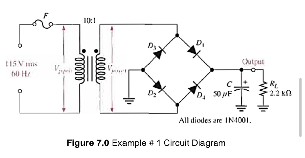
Determine the peak-to-peak ripple voltage if the filter capacitor in Figure 7.0 is increased to 100 µF and
the load resistance changes to 12 KΩ.
Transcribed Image Text:115 V mms
60 Hz
O
10:1
ellel
-40000
Visert
Output
с
D₁ 50 μF
All diodes are IN4001.
D₂
Figure 7.0 Example # 1 Circuit Diagram
www
R₂
2.2 ΚΩ
Expert Solution
This question has been solved!
Explore an expertly crafted, step-by-step solution for a thorough understanding of key concepts.

Step by step
Solved in 2 steps with 2 images

Knowledge Booster


Learn more about
Need a deep-dive on the concept behind this application? Look no further. Learn more about this topic, electrical-engineering and related others by exploring similar questions and additional content below.Recommended textbooks for you
Delmar's Standard Textbook Of Electricity
Electrical Engineering
ISBN:
9781337900348
Author:
Stephen L. Herman
Publisher:
Cengage Learning

Electricity for Refrigeration, Heating, and Air C…
Mechanical Engineering
ISBN:
9781337399128
Author:
Russell E. Smith
Publisher:
Cengage Learning

EBK ELECTRICAL WIRING RESIDENTIAL
Electrical Engineering
ISBN:
9781337516549
Author:
Simmons
Publisher:
CENGAGE LEARNING - CONSIGNMENT
Delmar's Standard Textbook Of Electricity
Electrical Engineering
ISBN:
9781337900348
Author:
Stephen L. Herman
Publisher:
Cengage Learning
Electricity for Refrigeration, Heating, and Air C…
Mechanical Engineering
ISBN:
9781337399128
Author:
Russell E. Smith
Publisher:
Cengage Learning
EBK ELECTRICAL WIRING RESIDENTIAL
Electrical Engineering
ISBN:
9781337516549
Author:
Simmons
Publisher:
CENGAGE LEARNING - CONSIGNMENT
