= 12 cos(200t) V in the following circuit. Use Thévenin's theorem where it will do the best Let v, and find: (a) Difference Equation for vc; (b) vc(t); (c) vc(t = 20 ms). You may assume all transients have died out long before t = 0. 4Ω ic + 6Ω 100 mF iR
= 12 cos(200t) V in the following circuit. Use Thévenin's theorem where it will do the best Let v, and find: (a) Difference Equation for vc; (b) vc(t); (c) vc(t = 20 ms). You may assume all transients have died out long before t = 0. 4Ω ic + 6Ω 100 mF iR

Delmar's Standard Textbook Of Electricity
7th Edition
ISBN:9781337900348
Author:Stephen L. Herman
Publisher:Stephen L. Herman
Chapter17: Resistive-inductive Series Circuits
Section: Chapter Questions
Problem 2PP: Assume that the voltage drop across the resistor, ER, is 78 V, that the voltage drop across the...

Related questions
Question
100%
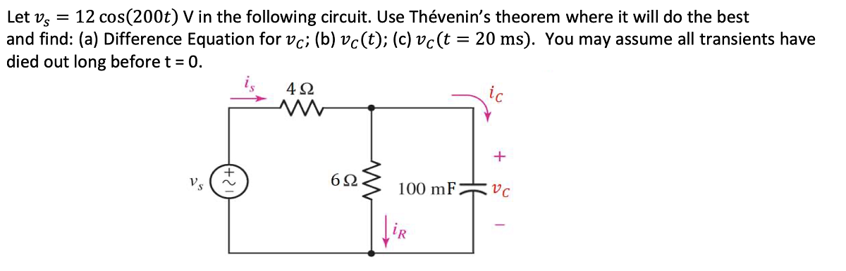
Transcribed Image Text:Let v, = 12 cos(200t) V in the following circuit. Use Thévenin's theorem where it will do the best
and find: (a) Difference Equation for vc; (b) vc(t); (c) vc(t = 20 ms). You may assume all transients have
died out long before t = 0.
4 2
ic
+
Vs
100 mF
Expert Solution
This question has been solved!
Explore an expertly crafted, step-by-step solution for a thorough understanding of key concepts.

Step by step
Solved in 4 steps with 4 images

Knowledge Booster


Learn more about
Need a deep-dive on the concept behind this application? Look no further. Learn more about this topic, electrical-engineering and related others by exploring similar questions and additional content below.Recommended textbooks for you
Delmar's Standard Textbook Of Electricity
Electrical Engineering
ISBN:
9781337900348
Author:
Stephen L. Herman
Publisher:
Cengage Learning
Delmar's Standard Textbook Of Electricity
Electrical Engineering
ISBN:
9781337900348
Author:
Stephen L. Herman
Publisher:
Cengage Learning