12. In the given circuit the current I, is 1) 0.4 A 2) - 0.4 A 30 3) 0.8 A 4) - 0.8 A 40 an 40 80
12. In the given circuit the current I, is 1) 0.4 A 2) - 0.4 A 30 3) 0.8 A 4) - 0.8 A 40 an 40 80

Power System Analysis and Design (MindTap Course List)
6th Edition
ISBN:9781305632134
Author:J. Duncan Glover, Thomas Overbye, Mulukutla S. Sarma
Publisher:J. Duncan Glover, Thomas Overbye, Mulukutla S. Sarma
Chapter2: Fundamentals
Section: Chapter Questions
Problem 2.17MCQ: Consider the load convention that is used for the RLC elements shown in Figure 2.2 of the text. A....

Related questions
Question
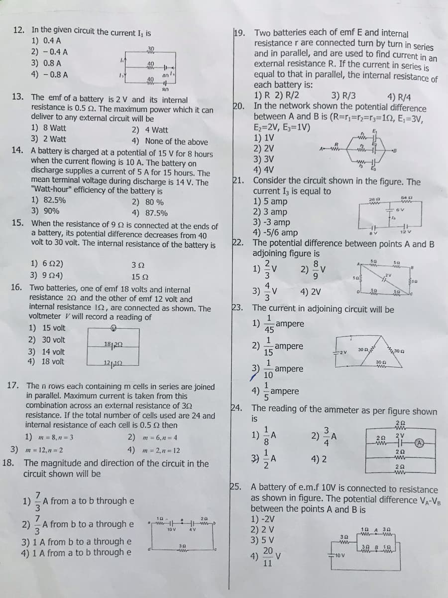
Transcribed Image Text:12. In the given circuit the current I¡ is
19. Two batteries each of emf E and internal
resistance r are connected turn by turn in series
and in parallel, and are used to find current in an
external resistance R. If the current in series is
equal to that in parallel, the internal resistance of
each battery is:
1) R 2) R/2
20. In the network shown the potential difference
between A and B is (R=r,=r2=r3=12, E;=3V,
Ez=2V, E3=1V)
1) 1V
2) 2V
3) 3V
4) 4V
21. Consider the circuit shown in the figure. The
current I3 is equal to
1) 5 amp
2) 3 amp
3) -3 amp
4) -5/6 amp
22. The potential difference between points A and B
adjoining figure is
1) 0.4 A
2) - 0.4 A
30
3) 0.8 A
4) - 0.8 A
40
an.
3) R/3
13. The emf of a battery is 2 V and its internal
resistance is 0.5 Q. The maximum power which it can
deliver to any external circuit will be
4) R/4
1) 8 Watt
2) 4 Watt
4) None of the above
E1
3) 2 Watt
14. A battery is charged at a potential of 15 V for 8 hours
when the current flowing is 10 A. The battery on
discharge supplies a current of 5 A for 15 hours. The
mean terminal voltage during discharge is 14 V. The
"Watt-hour" efficiency of the battery is
1) 82.5%
3) 90%
54 2
2) 80 %
4) 87.5%
15. When the resistance of 9 Q is connected at the ends of
a battery, its potential difference decreases from 40
volt to 30 volt. The internal resistance of the battery is
1) 6Ω2)
3) 9 04)
16. Two batteries, one of emf 18 volts and internal
resistance 22 and the other of emf 12 volt and
internal resistance 12, are connected as shown. The
voltmeter V will record a reading of
2.
1)
3
50
8.
2) v
9.
32
15 2
sa
4
3)
V
4) 2V
3
23. The current in adjoining circuit will be
1) 15 volt
1)
ampere
45
2) 30 volt
181202
2)
ampere
30 n
4,30 a
3) 14 volt
4) 18 volt
15
1
ampere
10
12112
30 n
17. The n rows each containing m cells in series are joined
in parallel. Maximum current is taken from this
combination across an external resistance of 32
1
4)
ampere
24. The reading of the ammeter as per figure shown
resistance. If the total number of cells used are 24 and
is
internal resistance of each cell is 0.5 2 then
3
1)
2) A
4
1) m = 8, n = 3
2) m = 6,n = 4
2V
3) m = 12,n = 2
4) m = 2,n = 12
3)
4) 2
20
ww
18. The magnitude and direction of the circuit in the
circuit shown will be
ww
25. A battery of e.m.f 10V is connected to resistance
as shown in figure. The potential difference VA-VB
between the points A and B is
1) -2V
2) 2 V
3) 5 V
20
1)
7
A from a to b through e
3
7
A from b to a through e
10
"ww iHwb
20
2)
3
10 A 30
ww w
10 V
30
ww
3) 1 A from b to a through e
4) 1 A from a to b through e
4)
V
10 V
11
1/81/2
Expert Solution
This question has been solved!
Explore an expertly crafted, step-by-step solution for a thorough understanding of key concepts.

Step by step
Solved in 2 steps

Knowledge Booster


Learn more about
Need a deep-dive on the concept behind this application? Look no further. Learn more about this topic, electrical-engineering and related others by exploring similar questions and additional content below.Recommended textbooks for you
Power System Analysis and Design (MindTap Course …
Electrical Engineering
ISBN:
9781305632134
Author:
J. Duncan Glover, Thomas Overbye, Mulukutla S. Sarma
Publisher:
Cengage Learning
Power System Analysis and Design (MindTap Course …
Electrical Engineering
ISBN:
9781305632134
Author:
J. Duncan Glover, Thomas Overbye, Mulukutla S. Sarma
Publisher:
Cengage Learning