13.15 Determine the voltage V. in the circuit shown in Figure 13-42 using Thevenin's. -j40 j8N 20 2 + Vx – 12 20° V 15 ΩS 4 20° A A o07 6 FIGURE 13-42: Circuit schematic for problem 13.15.
13.15 Determine the voltage V. in the circuit shown in Figure 13-42 using Thevenin's. -j40 j8N 20 2 + Vx – 12 20° V 15 ΩS 4 20° A A o07 6 FIGURE 13-42: Circuit schematic for problem 13.15.

Power System Analysis and Design (MindTap Course List)
6th Edition
ISBN:9781305632134
Author:J. Duncan Glover, Thomas Overbye, Mulukutla S. Sarma
Publisher:J. Duncan Glover, Thomas Overbye, Mulukutla S. Sarma
Chapter13: Transmission Lines: Transient Operation
Section: Chapter Questions
Problem 13.19P

Related questions

Question
Please Solve in steps
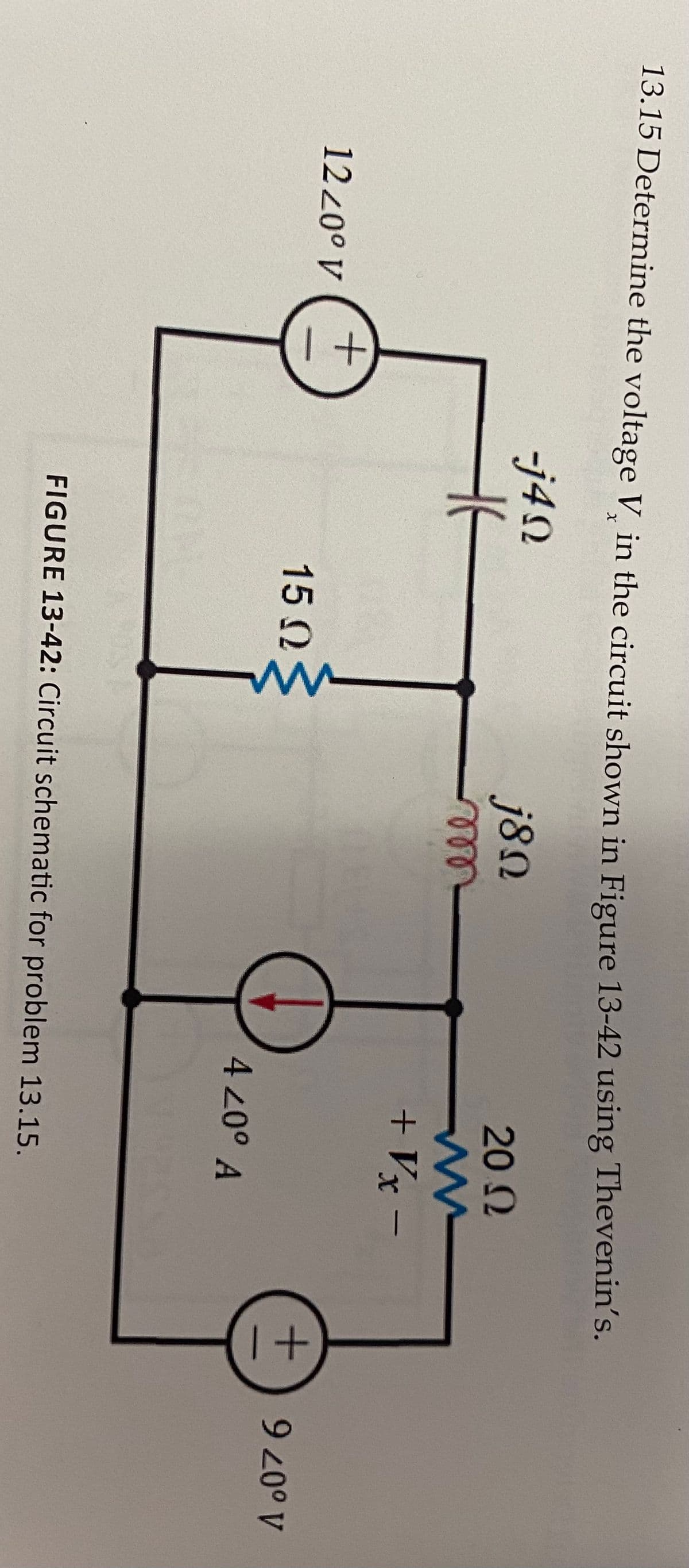
Transcribed Image Text:13.15 Determine the voltage V in the circuit shown in Figure 13-42 using Thevenin's.
-j4N
j8N
20 2
ell
+ Vx –
1220° V
15 N
4 20° A
A o07 6
FIGURE 13-42: Circuit schematic for problem 13.15.
Expert Solution
This question has been solved!
Explore an expertly crafted, step-by-step solution for a thorough understanding of key concepts.

Step by step
Solved in 3 steps with 3 images

Knowledge Booster


Learn more about
Need a deep-dive on the concept behind this application? Look no further. Learn more about this topic, electrical-engineering and related others by exploring similar questions and additional content below.Recommended textbooks for you
Power System Analysis and Design (MindTap Course …
Electrical Engineering
ISBN:
9781305632134
Author:
J. Duncan Glover, Thomas Overbye, Mulukutla S. Sarma
Publisher:
Cengage Learning
Power System Analysis and Design (MindTap Course …
Electrical Engineering
ISBN:
9781305632134
Author:
J. Duncan Glover, Thomas Overbye, Mulukutla S. Sarma
Publisher:
Cengage Learning