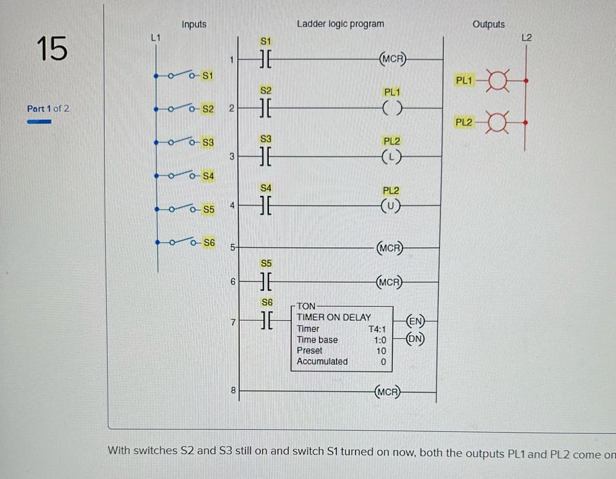
15 Part 1 of 2 L1 Inputs O O-S1 0-S2 2 O-S3 O O-S4 o-S5 1 o S6 3 5- 6 7 8 S1 HE S2 HF S3 HE S4 = HE S155 36 S6 36 Ladder logic program · ΤΟΝ TIMER ON DELAY Timer Time base Preset Accumulated (MCR) PL1 () PL2 PL2 (u) (MCR) (MCR) T4:1 1:0 10 0 MCR (EN) (ON) PL1 PL2 Outputs L2 OF With switches S2 and S3 still on and switch S1 turned on now, both the outputs PL1 and PL2 come o
15 Part 1 of 2 L1 Inputs O O-S1 0-S2 2 O-S3 O O-S4 o-S5 1 o S6 3 5- 6 7 8 S1 HE S2 HF S3 HE S4 = HE S155 36 S6 36 Ladder logic program · ΤΟΝ TIMER ON DELAY Timer Time base Preset Accumulated (MCR) PL1 () PL2 PL2 (u) (MCR) (MCR) T4:1 1:0 10 0 MCR (EN) (ON) PL1 PL2 Outputs L2 OF With switches S2 and S3 still on and switch S1 turned on now, both the outputs PL1 and PL2 come o

Chapter22: Sequence Control
Section: Chapter Questions
Problem 6SQ: Draw a symbol for a solid-state logic element AND.

Related questions
Question
100%
True or False Question
Transcribed Image Text:15
Part 1 of 2
L1
Inputs
o-S1
0-S2
$3
0-S4
o-S5
o-S6
1
2
3
4
5-
6
7
8
$1
HE
$2
36
$3
HE
S4
HE
S5
ISIS
HE
S6
Ladder logic program
· ΤΟΝ
TIMER ON DELAY
Timer
Time base
Preset
Accumulated
(MCR
PL1
()
PL2
PL2
S
-(MCR)
(MCR
T4:1
1:0
10
0
(MCR
(ON)
PL1
PL2
Outputs
a
L2
With switches S2 and S3 still on and switch S1 turned on now, both the outputs PL1 and PL2 come on
Expert Solution
This question has been solved!
Explore an expertly crafted, step-by-step solution for a thorough understanding of key concepts.

This is a popular solution!

Trending now
This is a popular solution!

Step by step
Solved in 2 steps

Knowledge Booster


Learn more about
Need a deep-dive on the concept behind this application? Look no further. Learn more about this topic, electrical-engineering and related others by exploring similar questions and additional content below.Recommended textbooks for you