16V for circuit shown in figure, find the current in each resister. Itag ce
16V for circuit shown in figure, find the current in each resister. Itag ce

Chapter19: Special-purpose Outlets-water Pump, Water Heater
Section19.2: Water Heater Branch Circuit
Problem 8R: For residential water heaters, the Consumer Product Safety Commission suggests a maximum temperature...

Related questions

Question
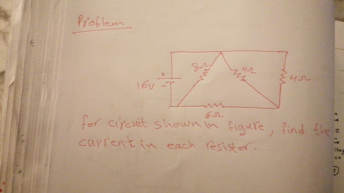
Transcribed Image Text:Problem
452
16V
for circuit shown in figure, find the
current in each resistor.
ce
Expert Solution
This question has been solved!
Explore an expertly crafted, step-by-step solution for a thorough understanding of key concepts.

Step by step
Solved in 3 steps with 2 images

Knowledge Booster


Learn more about
Need a deep-dive on the concept behind this application? Look no further. Learn more about this topic, electrical-engineering and related others by exploring similar questions and additional content below.Recommended textbooks for you
EBK ELECTRICAL WIRING RESIDENTIAL
Electrical Engineering
ISBN:
9781337516549
Author:
Simmons
Publisher:
CENGAGE LEARNING - CONSIGNMENT
EBK ELECTRICAL WIRING RESIDENTIAL
Electrical Engineering
ISBN:
9781337516549
Author:
Simmons
Publisher:
CENGAGE LEARNING - CONSIGNMENT