180%- 日2 在 會Q 回☆ 6 @ 213 (b) For the comparator circuit shown below, a sinusoidal input signal with a peak voltage (Vp) of 5 V and a frequency of 1 Hz is applied to the non-inverting terminal. Assume +Vcc as +12V and -Vcc as -12 V, with corresponding saturation voltages of +Vsat of +11 V and - Vsat of -11 V and R1 and R2 values of 100 kQ and 50 kN, respectively. Assuming that the signal frequency is well below the slew rate limit, describe and draw what would be the comparator output. +Vcc Vin 5 V VN + +Vcc I Vo R1 R2 1 s Vcc
180%- 日2 在 會Q 回☆ 6 @ 213 (b) For the comparator circuit shown below, a sinusoidal input signal with a peak voltage (Vp) of 5 V and a frequency of 1 Hz is applied to the non-inverting terminal. Assume +Vcc as +12V and -Vcc as -12 V, with corresponding saturation voltages of +Vsat of +11 V and - Vsat of -11 V and R1 and R2 values of 100 kQ and 50 kN, respectively. Assuming that the signal frequency is well below the slew rate limit, describe and draw what would be the comparator output. +Vcc Vin 5 V VN + +Vcc I Vo R1 R2 1 s Vcc

Introductory Circuit Analysis (13th Edition)
13th Edition
ISBN:9780133923605
Author:Robert L. Boylestad
Publisher:Robert L. Boylestad
Chapter1: Introduction
Section: Chapter Questions
Problem 1P: Visit your local library (at school or home) and describe the extent to which it provides literature...

Related questions

Question
Transcribed Image Text:Some practice questions for class test(1).pdf - Adobe Acrobat Reader DC (32-bit)
File
Edit
View Sign Window Help
Home
Tools
Some practice ques... x
UNIVERSITY OF UL..
早2 画Q
21
180%
Search 'Crop P
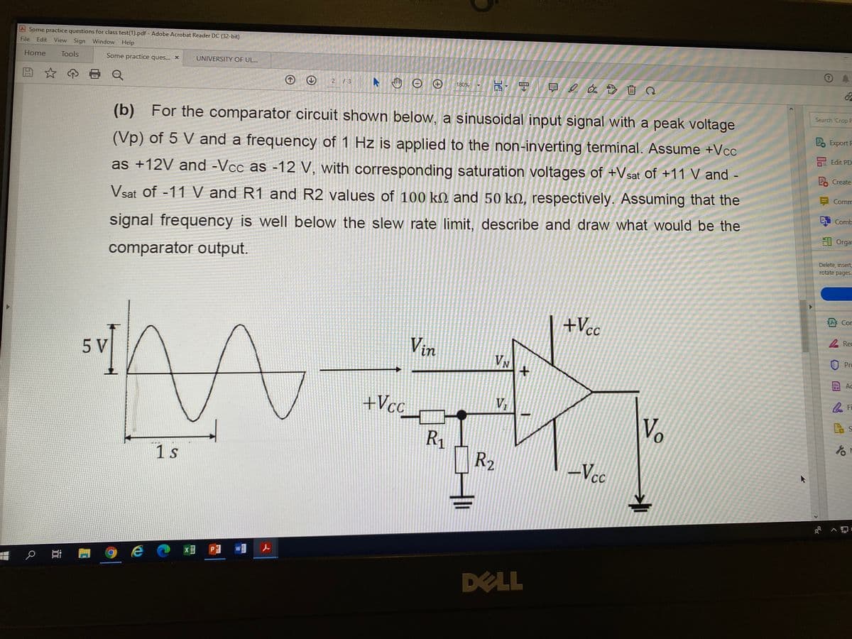
(b) For the comparator circuit shown below, a sinusoidal input signal with a peak voltage
P Export F
Edit PD
(Vp) of 5 V and a frequency of 1 Hz is applied to the non-inverting terminal. Assume +Vcc
Create
as +12V and -Vcc as -12 V, with corresponding saturation voltages of +Vsat of +11 V and -
Comm
Vsat of -11 V and R1 and R2 values of 100 kM and 50 kN, respectively. Assuming that the
i Comb
El Orgar
signal frequency is well below the slew rate limit, describe and draw what would be the
Delete, insert
rotate pages.
comparator output.
Cor
+Vcc
A Rec
Vin
Pro
5 V
VN
Ac
+Vcc
V
Vo
to
R1
R2
1 s
-Vcc
DELL
く
P.
近
Expert Solution
This question has been solved!
Explore an expertly crafted, step-by-step solution for a thorough understanding of key concepts.

Step by step
Solved in 3 steps with 3 images

Knowledge Booster


Learn more about
Need a deep-dive on the concept behind this application? Look no further. Learn more about this topic, electrical-engineering and related others by exploring similar questions and additional content below.Recommended textbooks for you
Introductory Circuit Analysis (13th Edition)
Electrical Engineering
ISBN:
9780133923605
Author:
Robert L. Boylestad
Publisher:
PEARSON

Delmar's Standard Textbook Of Electricity
Electrical Engineering
ISBN:
9781337900348
Author:
Stephen L. Herman
Publisher:
Cengage Learning

Programmable Logic Controllers
Electrical Engineering
ISBN:
9780073373843
Author:
Frank D. Petruzella
Publisher:
McGraw-Hill Education
Introductory Circuit Analysis (13th Edition)
Electrical Engineering
ISBN:
9780133923605
Author:
Robert L. Boylestad
Publisher:
PEARSON
Delmar's Standard Textbook Of Electricity
Electrical Engineering
ISBN:
9781337900348
Author:
Stephen L. Herman
Publisher:
Cengage Learning
Programmable Logic Controllers
Electrical Engineering
ISBN:
9780073373843
Author:
Frank D. Petruzella
Publisher:
McGraw-Hill Education

Fundamentals of Electric Circuits
Electrical Engineering
ISBN:
9780078028229
Author:
Charles K Alexander, Matthew Sadiku
Publisher:
McGraw-Hill Education

Electric Circuits. (11th Edition)
Electrical Engineering
ISBN:
9780134746968
Author:
James W. Nilsson, Susan Riedel
Publisher:
PEARSON

Engineering Electromagnetics
Electrical Engineering
ISBN:
9780078028151
Author:
Hayt, William H. (william Hart), Jr, BUCK, John A.
Publisher:
Mcgraw-hill Education,