2. For the beam shown, derive the expression for V and M. 120 N/m A B 8m- 6 m
2. For the beam shown, derive the expression for V and M. 120 N/m A B 8m- 6 m

International Edition---engineering Mechanics: Statics, 4th Edition
4th Edition
ISBN:9781305501607
Author:Andrew Pytel And Jaan Kiusalaas
Publisher:Andrew Pytel And Jaan Kiusalaas
Chapter9: Moments And Products Of Inertia Of Areas
Section: Chapter Questions
Problem 9.16P: Figure (a) shows the cross-sectional dimensions for the structural steel section known as C1020...

Related questions
Question
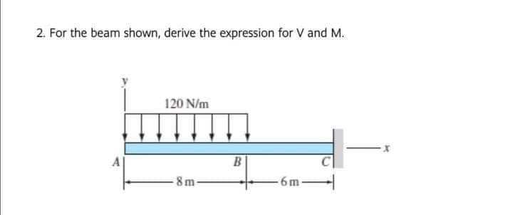
Transcribed Image Text:2. For the beam shown, derive the expression for V and M.
120 N/m
A
8 m-
6m
Expert Solution
This question has been solved!
Explore an expertly crafted, step-by-step solution for a thorough understanding of key concepts.

Step by step
Solved in 2 steps with 2 images

Knowledge Booster


Learn more about
Need a deep-dive on the concept behind this application? Look no further. Learn more about this topic, mechanical-engineering and related others by exploring similar questions and additional content below.Recommended textbooks for you
International Edition---engineering Mechanics: St…
Mechanical Engineering
ISBN:
9781305501607
Author:
Andrew Pytel And Jaan Kiusalaas
Publisher:
CENGAGE L
International Edition---engineering Mechanics: St…
Mechanical Engineering
ISBN:
9781305501607
Author:
Andrew Pytel And Jaan Kiusalaas
Publisher:
CENGAGE L