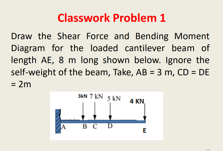
Draw the Shear Force and Bending Moment Diagram for the loaded cantilever beam of length AE, 8 m long shown below. Ignore the self-weight of the beam, Take, AB = 3 m, CD = DE %3D = 2m
Q: Calculate the maximum def lection δmaxof a uniformly loaded simple beam if the spanlength L = 2.0 m,…
A: Given Load, q = 2 kN/m Length, L = 2 m E = 70 GPa Find Maximum deflection
Q: Calculate the shear force and bending moment for the simply supported beam of length 8m with the…
A:
Q: 6KN/m Q4 /For the beam loaded as shown in fig. draw shear force diagram and bending moment diagram…
A:
Q: 1. The cantilever beam AH is acted upon by a uniformly distributed downward load of intensity…
A: This is a cantilever beam so, the maximum shear force and bending moment will be at the fixed end.…
Q: A simply supported beam AB has a length of 3 m and carries distributed load which varies in linear…
A: Given: The length of beam, L = 3 m The intensity of load at A, w1 = 1.5w The intensity of load at…
Q: Refer to the beam shown below. P = 94.50 kN 75 P (kN) 60 kN/m kN/m 2m 1m 3m 3m 90 kN.m A C D E a)…
A:
Q: 6.. A cantilever beam is 2.5 m long, and carries a concentrated load of 380 N at its midpoint, and…
A:
Q: A beam ABC with an overhang at one end supports a uniform load of intensity P= 13.8 kN/m and a…
A: Given, The length of the beam is 4.8 m.
Q: Draw shear force digam and bending moment digram for the following beam 300 N 500 N 800 N to to 0.5…
A: A cantilever support will exert horizontal component of reaction, vertical component of reaction and…
Q: The simple beam AB, shown below, supports a concentrated load of 22 kN and a segment of a…
A:
Q: Get the shear and moment function and draw the shear and moment diagram for the beam. A simply…
A: Givensimply supported beamL=8Mw1=5kN/mw2=10kN/mP1=10kNM1=20kNm
Q: 10KN/m 7,5m B (A 15m iom
A: Objective: To calculate normal force, shear force, and bending moment about point D.
Q: a)A simply supported beam of length 6 m ,carries point load of 3 kN 4 m from the left end. Draw the…
A:
Q: Draw the shear and moment diagram of the overhanging beam shown below. For this part, please show…
A: Draw a diagram showing the beam support reactions. Here, RA and RB are the reactions at supports A…
Q: A cantilerver beam AB, 2.5 m long carries a uniformly distributed load of 2 kN/m over a length of 2…
A:
Q: Draw the shear-force and bending-momentdiagrams for a cantilever beam AB carrying a uniformload of…
A:
Q: A cantilever beam 2m span carries point loads as shown. Draw the shear force and bending moment…
A:
Q: SHOW THE FOLLOWING: 1. COMPUTATION OF REACTIONS 2. SHEAR AND MOMENT DIAGRAM 3. MAXIMUM BENDING…
A:
Q: The 8 m long cantilever beam shown in the figure below carries a uniformly distributed load of 10…
A:
Q: Please draw shear force diagram and bending moment diagram for the following beam and also indicate…
A: Draw the free body diagram of the beam.
Q: Draw the shear force and bending moment diagrams of the beam shown and find the bending moment M in…
A:
Q: Draw the shear force and the bending moment diagrams for the simply supported beam loaded with a…
A: Shear force diagram represents shear force at every section of the beam. Shear force at any…
Q: 0.2m TOKN 20K 5KN/m D E Im A 2m 3m Im B
A:
Q: A beam 12 m is simply and symmetrically supported over a span of 8 m. it carrier concentrated loads…
A: For solution refer below images.
Q: Refer to the beam shown below. q = 24 kN/m andP = 94.50 kN %3D 9 (kN/m) P (kN) B -3 m -6 m- a)…
A:
Q: Draw the complete shearing force and bending moment diagram for the beam shown in figure. Show…
A:
Q: 3) For the beam and distributed loading shown below determine a)- Moment equation M(x), b)- shear…
A:
Q: 6 kN/m 3 m 3 m B 1 m Figure 1 shown the T- shape beam is exerted with the distributed load. Given…
A:
Q: A beam of 8 m long, loaded with uniformly distributed load on the 4 m span CE with a concentrated…
A: Given dataSN = Student NumberTotal length fo the beam L = 8mBending moment = SN (kN)To draw the…
Q: A simply supported beam of length 6m carries two point loads of magnitude 1KN and 4KN at a distance…
A: To determine the reaction at both the supports, we must apply the statics equations: Summation of…
Q: А C 2а
A:
Q: A cantilever beam 2m span carries point loads as shown. Draw the shear force and bending moment…
A:
Q: Draw the shear and moment diagram of the cantilever beam shown below. For this part, please show the…
A: Consider upward force & CW moment as (+)ve and downward force & CCW moment as (-)ve. Let…
Q: 3" 14' (0.9m) [4.2 m) 1000 Ib/tt [14.6 kN/m] R2 (b)
A:
Q: A simply supported beam with length L = 4.0 m carries a uniform load w = 2.5 kN/m and a concentrated…
A:
Q: A beam of uniform rectangular cross-section is fixed at one end and carries an electric motor…
A:
Q: (a) A simply supported beam of length 6 m carries point loads of 5 kN each at a distance of 1.5 m…
A: The beam explained in the problem can be sketched as follows,
Q: A beam ABC with an overhang at one end supports a uniform load of intensity P= 13.8 kN/m and a…
A: Draw free body diagram of beam Determine reactions at A and B using equilibrium equations
Q: A 6-m simply supported beam AB supports a trapezoidal distributed load. The intensity of the load…
A:
Q: Draw the Shear Force and Bending Moment Diagram for the loaded cantilever beam of length AE, 8 m…
A:
Q: 25. A fiberglass pipe is lifted by a sling, as shown in the figure. The outer diameter of the pipe…
A: Given data as per questionLength of pipe =10 ms=4 md2=100 mmd1=100−12=88 mmweight density =1500…
Q: A cantilever beam of length 2 m carries the point loads as shown in Fig 2. Draw the shear force and…
A:
Q: A beam of 8 m long, loaded with uniformly distributed load on the 4 m span CE with a concentrated…
A:
Q: Q#4: A continuous beam AB, 6 m long having three supports is loaded as shown in Fig.2. Construct the…
A: In this solution you may find the difficulty as the value of x varies from 0 to 1.5 in each portion…
Q: F= 100 kN, L= 8m, b = 10 mm and h = 20 mm for sugar loading of the beam. In this case, the…
A: The load applied on the beam is, F=100 kN The length of the beam is, L=8 m The breadth of the beam…
Q: Obtain an expression for the maximum bending moment at a section of the girder at a distance of z…
A:
Q: A horizontal beam AE, 12 m long and it carries a uniformly distributed load of 3.8 kN/m over the…
A:
Q: For the beam shown, derive the expressions for V and M, and draw the shear force and bending moment…
A: Given
Q: Analyze the cantilever beam loaded as shown below, use area-moment method 50 kN 100 kN В 400 kN.m. A…
A: For solution refer below images.
Trending now
This is a popular solution!
Step by step
Solved in 3 steps with 2 images
- A simple beam ACE is constructed with square cross sections and a double taper (see figure). The depth of the beam at the supports is dAand at the midpoint is dc= 2d 4. Each half of the beam has length L. Thus, the depth and moment of inertia / at distance x from the left-hand end are, respectively, in which IAis the moment of inertia at end A of the beam. (These equations are valid for .x between 0 and L, that is, for the left-hand half of the beam.) Obtain equations for the slope and deflection of the left-hand half of the beam due to the uniform load. From the equations in part (a), obtain formulas for the angle of rotation 94at support A and the deflection Scat the midpoint.A weight W = 4000 lb falls through a height h = 0.5 in, onto the midpoint of a simple beam of length L = 10 ft (see figure). Assuming that the allowable bending stress in the beam is = 18,000 psi and E = 30 x 10* psi, select the lightest wide-flange beam listed in Table F-l(a) in Appendix F that will be satisfactory.A frame ABCD is constructed of steel wide-flange members (W8 x 21; E = 30 x ID6 psi) and subjected to triangularly distributed loads of maximum intensity q0acting along the vertical members (see figure). The distance between supports is L = 20 ft and the height of the frame is h = 4 ft. The members are rigidly connected at B and C. Calculate the intensity of load q0 required to produce a maximum bending moment of 80 kip-in. in the horizontal member BC. If the load q0 is reduced to one-half of the value calculated in part (a), what is the maximum bending moment in member BC? What is the ratio of this moment to the moment of 80 kip-in. in part (a)?
- .2 A ligmio.irc ii supported by two vorlical beams consistins: of thin-walled, tapered circular lubes (see ligure part at. for purposes of this analysis, each beam may be represented as a cantilever AB of length L = 8.0 m subjected to a lateral load P = 2.4 kN at the free end. The tubes have a constant thickness ; = 10.0 mm and average diameters dA = 90 mm and dB = 270 mm at ends A and B, re s pec lively. Because the thickness is small compared to the diameters, the moment of inerlia at any cross section may be obtained from the formula / = jrrf3;/8 (see Case 22, Appendix E); therefore, the section modulus mav be obtained from the formula S = trdhlA. (a) At what dislance A from the free end docs the maximum bending stress occur? What is the magnitude trllul of the maximum bending stress? What is the ratio of the maximum stress to the largest stress (b) Repeat part (a) if concentrated load P is applied upward at A and downward uniform load q {-x) = 2PIL is applied over the entire beam as shown in the figure part b What is the ratio of the maximum stress to the stress at the location of maximum moment?A two-axle carriage that is part of an over head traveling crane in a testing laboratory moves slowly across a simple beam AB (sec figure). The load transmitted to the beam from the front axle is 2200 lb and from the rear axle is 3800 lb. The weight of the beam itself may be disregarded. Determine the minimum required section modulus S for the beam if the allowable bending stress is 17,0 ksi, the length of the beam is 18 ft, and the wheelbase of the carriage is 5 ft. Select the most economical I-beam (S shape) from Table F-2(a), Appendix F.A rectangular beam with notches and a hole (see figure) has dimensions h = 5.5 in., h1= 5 in., and width b = 1.6 in. The beam is subjected to a bending moment M = 130 kip-in., and the maximum allowable bending stress in the material (steel) is emax = 42,000 psi. What is the smallest radius Rminthat should be used in the notches? What is the diameter dmixof the largest hole that should be drilled at the mid height of the beam?
- The hollow box beam shown in the figure is subjected to a bending moment M of such magnitude that the flanges yield but the webs remain linearly elastic. (a) Calculate the magnitude of the moment M if the dimensions of the cross section are A = 15 in., A] = 12.75 in., h = 9 in., and ey =7.5 in. Also, the yield stress is eY = 33 ksi. (b) What percent of the moment M is produced by the elastic core?A weight W = 20 kN falls through a height h = 1,0 mm onto the midpoint or a simple beam of length L = 3 m (see figure). The beam is made of wood with square cross section (dimension don each side) and E = 12 GPa. If the allowable bending stress in the wood is °aLLow =10MPa, what is the minimum required dimensionA heavy object of weight W is dropped onto the midpoint of a simple beam AB from a height h (see figure). Obtain a formula for the maximum bending stress ^ma* due to tne filing weight in terms of h, st, and 5st, where it is the maximum bending stress and Sstis the deflection at the midpoint when the weight W acts on the beam as a statically applied load. Plot a graph of the ratio o"max/ö"it (that is, the ratio of the dynamic stress to the static stress) versus the ratio iifS^r(Let h/S^ vary from 0 to 10.)
- An overhanging beam ABC with a rectangular cross section has the dimensions shown in the figure. A weight W = 750 N drops onto end C of the beam. If the allowable normal stress in bending is 45 MPa, what is the maximum height h from which the weight may be dropped? (Assume E = 12 G Pa,)A rectangular beam with semicircular notches, as shown in part b of the figure, has dimensions h = 0,88 in. and h1 = 0.80 in. The maximum allowable bending stress in the metal beam is emax = 60 ksi, and the bending moment is M = 600 lb-in. Determine the minimum permissible width bminof the beam.A hollow box beam with height h = 16 in,, width h = 8 in,, and constant wall thickness r = 0.75 LiL is shown in the figure. The beam is constructed of steel with yield stress ty = 32 ksi. Determine the yield moment My, plastic moment A/p, and shape factor.