Using the coordinate axes shown, write equations for the shear V and bending moment M for any section In the interval 0sI55 ft of the beam shown in Fig. 300 Ib/ft 200 lb/ft 5 ft 5 ft
Using the coordinate axes shown, write equations for the shear V and bending moment M for any section In the interval 0sI55 ft of the beam shown in Fig. 300 Ib/ft 200 lb/ft 5 ft 5 ft

International Edition---engineering Mechanics: Statics, 4th Edition
4th Edition
ISBN:9781305501607
Author:Andrew Pytel And Jaan Kiusalaas
Publisher:Andrew Pytel And Jaan Kiusalaas
Chapter6: Beams And Cables
Section: Chapter Questions
Problem 6.49P: Construct the shear force and bending moment diagrams for the beam shown by the area method. Neglect...

Related questions
Question
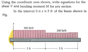
Transcribed Image Text:Using the coordinate axes shown, write equations for the
shear V and bending moment M for any section
In the interval 0sI55 ft of the beam shown in
Fig.
300 Ib/ft
200 lb/ft
5 ft
5 ft
Expert Solution
This question has been solved!
Explore an expertly crafted, step-by-step solution for a thorough understanding of key concepts.

This is a popular solution!

Trending now
This is a popular solution!

Step by step
Solved in 3 steps with 5 images

Recommended textbooks for you
International Edition---engineering Mechanics: St…
Mechanical Engineering
ISBN:
9781305501607
Author:
Andrew Pytel And Jaan Kiusalaas
Publisher:
CENGAGE L
International Edition---engineering Mechanics: St…
Mechanical Engineering
ISBN:
9781305501607
Author:
Andrew Pytel And Jaan Kiusalaas
Publisher:
CENGAGE L