2. Solve for the tensile force (in KN) acting inside the cable and the reaction (in KN) at hinge. PULLEY- cable s Lft 30 2L ft G kN/m (M+G) kN/m
2. Solve for the tensile force (in KN) acting inside the cable and the reaction (in KN) at hinge. PULLEY- cable s Lft 30 2L ft G kN/m (M+G) kN/m

International Edition---engineering Mechanics: Statics, 4th Edition
4th Edition
ISBN:9781305501607
Author:Andrew Pytel And Jaan Kiusalaas
Publisher:Andrew Pytel And Jaan Kiusalaas
Chapter6: Beams And Cables
Section: Chapter Questions
Problem 6.65P: Cable AB supports the uniformly distributed load of 4 kN/m. If the slope of the cable at A is zero,...

Related questions
Question
G=4
M=7
L=7
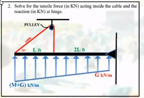
Transcribed Image Text:2. Solve for the tensile force (in KN) acting inside the cable and the
reaction (in KN) at hinge.
PULLEY
cable
30
Lft
2L ft
G kN/m
(M+G) kN/m
Expert Solution
This question has been solved!
Explore an expertly crafted, step-by-step solution for a thorough understanding of key concepts.

Step by step
Solved in 3 steps with 2 images

Recommended textbooks for you
International Edition---engineering Mechanics: St…
Mechanical Engineering
ISBN:
9781305501607
Author:
Andrew Pytel And Jaan Kiusalaas
Publisher:
CENGAGE L
International Edition---engineering Mechanics: St…
Mechanical Engineering
ISBN:
9781305501607
Author:
Andrew Pytel And Jaan Kiusalaas
Publisher:
CENGAGE L