2. The circuit shown in Figure-2 is at steady state before the switch closes at time t= 0. The input to the circuit is the voltage of the voltage source, 12 V. The output of this circuit is the voltage across the capacitor, v(t). 1. Determine v(t) for t>0. 10 kn 12 V 60 k
2. The circuit shown in Figure-2 is at steady state before the switch closes at time t= 0. The input to the circuit is the voltage of the voltage source, 12 V. The output of this circuit is the voltage across the capacitor, v(t). 1. Determine v(t) for t>0. 10 kn 12 V 60 k

Introductory Circuit Analysis (13th Edition)
13th Edition
ISBN:9780133923605
Author:Robert L. Boylestad
Publisher:Robert L. Boylestad
Chapter1: Introduction
Section: Chapter Questions
Problem 1P: Visit your local library (at school or home) and describe the extent to which it provides literature...

Related questions

Concept explainers
Synchronous Generator
In comparison to an asynchronous generator, it is a machine where the rotor speed is equal to the rotating magnetic field produced by the stator, i.e., mechanical speed is equal to the electrical speed, thus called synchronous, and not asynchronous.
Salient Pole Rotor
Salient pole rotor includes a large number of exposed poles mounted on a magnetic wheel. The construction of a bright pole is as shown in the image on the left. The proposed poles are made of metal laminations. The rotor winding is provided on these poles and is supported by pole shoes.
Question
can you solve this question only part a? if you write well I will be greateful.
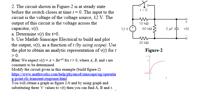
Transcribed Image Text:2. The circuit shown in Figure-2 is at steady state
before the switch closes at time t= 0. The input to the
circuit is the voltage of the voltage source, 12 V. The
output of this circuit is the voltage across the
capacitor, v(t).
a. Determine v(t) for t>0.
b. Use Matlab Simscape Electrical to build and plot
the output, v(t), as a function of t (by using scope). Use
the plot to obtain an analytic representation of v(t) for t
>0.
10 ka
12 V
60 k2
2 μΕ
v(t)
30 k2
Figure-2
Hint: We expect v(1) = A + Bet for t > 0, where A, B, and z are
constants to be determined.
Modify the circuit given in this example (build figure-2)
https://www.mathworks.com/help/physmod/simscape/ug/operatin
g-point-rlc-transient-response.html
You will obtain a graph as figure 2-b and by using graph and
substituting three 't' values to v(t) then you can find A, B and r.
Expert Solution
This question has been solved!
Explore an expertly crafted, step-by-step solution for a thorough understanding of key concepts.

Step by step
Solved in 3 steps with 3 images

Knowledge Booster


Learn more about
Need a deep-dive on the concept behind this application? Look no further. Learn more about this topic, electrical-engineering and related others by exploring similar questions and additional content below.Recommended textbooks for you
Introductory Circuit Analysis (13th Edition)
Electrical Engineering
ISBN:
9780133923605
Author:
Robert L. Boylestad
Publisher:
PEARSON

Delmar's Standard Textbook Of Electricity
Electrical Engineering
ISBN:
9781337900348
Author:
Stephen L. Herman
Publisher:
Cengage Learning

Programmable Logic Controllers
Electrical Engineering
ISBN:
9780073373843
Author:
Frank D. Petruzella
Publisher:
McGraw-Hill Education
Introductory Circuit Analysis (13th Edition)
Electrical Engineering
ISBN:
9780133923605
Author:
Robert L. Boylestad
Publisher:
PEARSON
Delmar's Standard Textbook Of Electricity
Electrical Engineering
ISBN:
9781337900348
Author:
Stephen L. Herman
Publisher:
Cengage Learning
Programmable Logic Controllers
Electrical Engineering
ISBN:
9780073373843
Author:
Frank D. Petruzella
Publisher:
McGraw-Hill Education

Fundamentals of Electric Circuits
Electrical Engineering
ISBN:
9780078028229
Author:
Charles K Alexander, Matthew Sadiku
Publisher:
McGraw-Hill Education

Electric Circuits. (11th Edition)
Electrical Engineering
ISBN:
9780134746968
Author:
James W. Nilsson, Susan Riedel
Publisher:
PEARSON

Engineering Electromagnetics
Electrical Engineering
ISBN:
9780078028151
Author:
Hayt, William H. (william Hart), Jr, BUCK, John A.
Publisher:
Mcgraw-hill Education,