2. The initial current through the inductor at t = 0 in the circuit shown in following Figure is 2 mA. Current I, is applied at t = 0, /s = 5 u(t) mA. a. Find current i(t), t≥ 0, through the inductor and plot i(t). b. Find voltage v(t), t≥ 0, across the inductor and plot v(t). R₂ R₁ ww 5 ΚΩ ww 2 ΚΩ 5 mA R₁ 10 ΚΩ ww R₂ 10 ΚΩ Hi lo-2 mA i(t) L 10mH v(t)
2. The initial current through the inductor at t = 0 in the circuit shown in following Figure is 2 mA. Current I, is applied at t = 0, /s = 5 u(t) mA. a. Find current i(t), t≥ 0, through the inductor and plot i(t). b. Find voltage v(t), t≥ 0, across the inductor and plot v(t). R₂ R₁ ww 5 ΚΩ ww 2 ΚΩ 5 mA R₁ 10 ΚΩ ww R₂ 10 ΚΩ Hi lo-2 mA i(t) L 10mH v(t)

Delmar's Standard Textbook Of Electricity
7th Edition
ISBN:9781337900348
Author:Stephen L. Herman
Publisher:Stephen L. Herman
Chapter18: Resistive-inductive Parallel Circuits
Section: Chapter Questions
Problem 2PP: Assume that the current flow through the resistor, IR, is 15 A; the current flow through the...

Related questions
Question
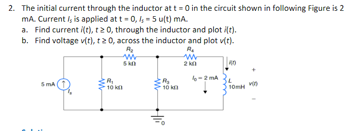
Transcribed Image Text:2. The initial current through the inductor at t = 0 in the circuit shown in following Figure is 2
mA. Current Is is applied at t = 0, /5 = 5 u(t) mA.
a. Find current i(t), t≥ 0, through the inductor and plot i(t).
b. Find voltage v(t), t≥ 0, across the inductor and plot v(t).
R₂
R₁
ww
ww
2 ΚΩ
5 ΚΩ
5 mA (1
R₁
10 ΚΩ
ww
R₂
10 kn
Hii
lo-2 mA
i(t)
L
10mH
v(t)
Expert Solution
This question has been solved!
Explore an expertly crafted, step-by-step solution for a thorough understanding of key concepts.

This is a popular solution!

Trending now
This is a popular solution!

Step by step
Solved in 5 steps with 17 images

Recommended textbooks for you
Delmar's Standard Textbook Of Electricity
Electrical Engineering
ISBN:
9781337900348
Author:
Stephen L. Herman
Publisher:
Cengage Learning
Delmar's Standard Textbook Of Electricity
Electrical Engineering
ISBN:
9781337900348
Author:
Stephen L. Herman
Publisher:
Cengage Learning