2.1) Design a BJT common-emitter amplifier (use the figure A or B in former page!) with a gain of 9. The Q point parameters should be IC = 3 mA and VCE = 8 V. A power supply of 20 V is available. Manufacturers' spec sheets give: min = 100, hte = 200.Take VBE = 0.7 V.
2.1) Design a BJT common-emitter amplifier (use the figure A or B in former page!) with a gain of 9. The Q point parameters should be IC = 3 mA and VCE = 8 V. A power supply of 20 V is available. Manufacturers' spec sheets give: min = 100, hte = 200.Take VBE = 0.7 V.

Introductory Circuit Analysis (13th Edition)
13th Edition
ISBN:9780133923605
Author:Robert L. Boylestad
Publisher:Robert L. Boylestad
Chapter1: Introduction
Section: Chapter Questions
Problem 1P: Visit your local library (at school or home) and describe the extent to which it provides literature...

Related questions
Question
Transcribed Image Text:2.1) Design a BJT common-emitter amplifier (use the figure A or B in former page!)
with a gain of 9. The Q point parameters should be IC = 3 mA and VCE = ŠV.
A power supply of 20 V is available. Manufacturers' spec sheets give:
min = 100, ht. = 200.Take VBE = 0.7 V.
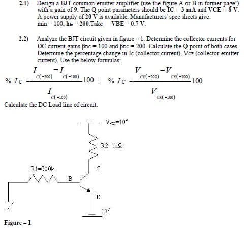
2.2) Analyze the BJT circuit given in figure – 1. Determine the collector currents for
DC current gains Boc = 100 and BDc = 200. Calculate the Q point of both cases.
Detemine the percentage change in Ic (collector current), Vcz (collector-emitter
current). Use the below formulas:
I
-I
V
-V
CE -100) 100
d-200) -100) 100 : % Ic
CE( -200)
% Ic
I
(-100)
Calculate the DC Load line of circuit.
CE( -100)
Voc-10"
R2=1k2
R1=300k
10V
Figure – 1
Expert Solution
This question has been solved!
Explore an expertly crafted, step-by-step solution for a thorough understanding of key concepts.

Step by step
Solved in 4 steps with 4 images

Knowledge Booster


Learn more about
Need a deep-dive on the concept behind this application? Look no further. Learn more about this topic, electrical-engineering and related others by exploring similar questions and additional content below.Recommended textbooks for you
Introductory Circuit Analysis (13th Edition)
Electrical Engineering
ISBN:
9780133923605
Author:
Robert L. Boylestad
Publisher:
PEARSON

Delmar's Standard Textbook Of Electricity
Electrical Engineering
ISBN:
9781337900348
Author:
Stephen L. Herman
Publisher:
Cengage Learning

Programmable Logic Controllers
Electrical Engineering
ISBN:
9780073373843
Author:
Frank D. Petruzella
Publisher:
McGraw-Hill Education
Introductory Circuit Analysis (13th Edition)
Electrical Engineering
ISBN:
9780133923605
Author:
Robert L. Boylestad
Publisher:
PEARSON
Delmar's Standard Textbook Of Electricity
Electrical Engineering
ISBN:
9781337900348
Author:
Stephen L. Herman
Publisher:
Cengage Learning
Programmable Logic Controllers
Electrical Engineering
ISBN:
9780073373843
Author:
Frank D. Petruzella
Publisher:
McGraw-Hill Education

Fundamentals of Electric Circuits
Electrical Engineering
ISBN:
9780078028229
Author:
Charles K Alexander, Matthew Sadiku
Publisher:
McGraw-Hill Education

Electric Circuits. (11th Edition)
Electrical Engineering
ISBN:
9780134746968
Author:
James W. Nilsson, Susan Riedel
Publisher:
PEARSON

Engineering Electromagnetics
Electrical Engineering
ISBN:
9780078028151
Author:
Hayt, William H. (william Hart), Jr, BUCK, John A.
Publisher:
Mcgraw-hill Education,