3 L X x 5 ام 1-Motor; 2,6-Coupling; 3-Reducer; 4-High speed gear pair; 5-Low speed gear pair; 7-Conveyor roller Figure 10-26 The diagram of belt conveyor transmission
3 L X x 5 ام 1-Motor; 2,6-Coupling; 3-Reducer; 4-High speed gear pair; 5-Low speed gear pair; 7-Conveyor roller Figure 10-26 The diagram of belt conveyor transmission

Automotive Technology: A Systems Approach (MindTap Course List)
6th Edition
ISBN:9781133612315
Author:Jack Erjavec, Rob Thompson
Publisher:Jack Erjavec, Rob Thompson
Chapter47: Steering Systems
Section: Chapter Questions
Problem 4RQ: Define the term gearbox ratio.

Related questions

Question
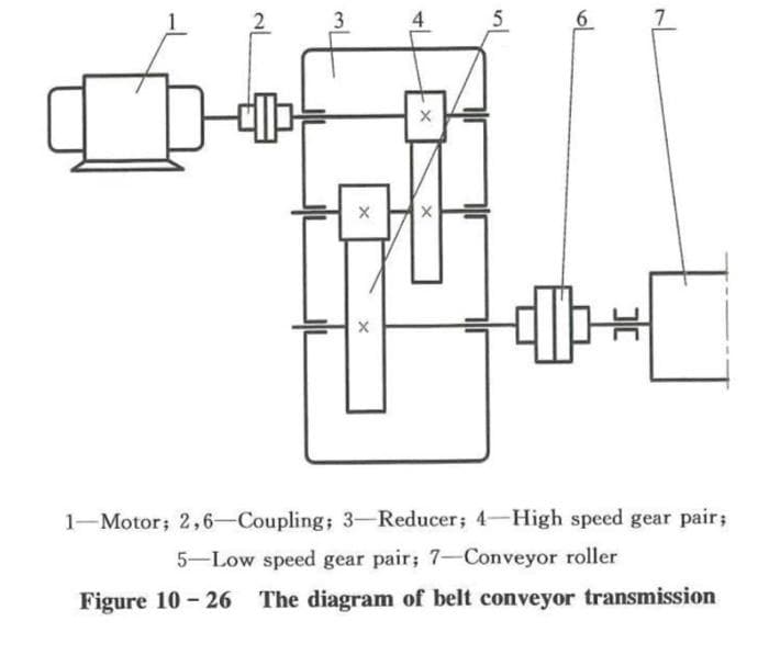
As shown in Figure 10-26, Please design a gear pair in the reducer of this belt conveyor. The input power is P=60 kW, the rotary speed of pinion is n1=960 r/min, the ration of teeth number is u= 2.5, the reducer is driven by electric motor. the design life is expected 10 years. the belt conveyor runs 12 hours per day. the load is stable.
Transcribed Image Text:3
4
1-Motor; 2,6-Coupling; 3-Reducer; 4-High speed gear pair;
5-Low speed gear pair; 7-Conveyor roller
Figure 10 - 26 The diagram of belt conveyor transmission
Expert Solution
This question has been solved!
Explore an expertly crafted, step-by-step solution for a thorough understanding of key concepts.

Step by step
Solved in 3 steps with 5 images

Knowledge Booster


Learn more about
Need a deep-dive on the concept behind this application? Look no further. Learn more about this topic, mechanical-engineering and related others by exploring similar questions and additional content below.Recommended textbooks for you
Automotive Technology: A Systems Approach (MindTa…
Mechanical Engineering
ISBN:
9781133612315
Author:
Jack Erjavec, Rob Thompson
Publisher:
Cengage Learning
Automotive Technology: A Systems Approach (MindTa…
Mechanical Engineering
ISBN:
9781133612315
Author:
Jack Erjavec, Rob Thompson
Publisher:
Cengage Learning