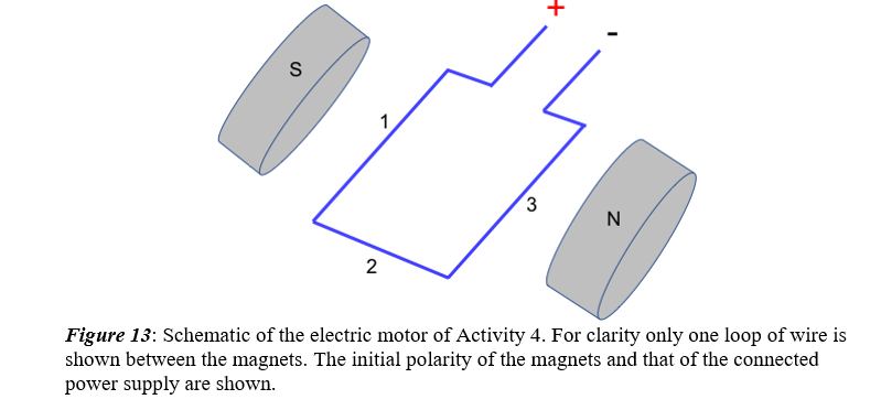
3 N 2 Figure 13: Schematic of the electric motor of Activity 4. For clarity only one loop of wire is shown between the magnets. The initial polarity of the magnets and that of the connected power supply are shown.
3 N 2 Figure 13: Schematic of the electric motor of Activity 4. For clarity only one loop of wire is shown between the magnets. The initial polarity of the magnets and that of the connected power supply are shown.

College Physics
1st Edition
ISBN:9781938168000
Author:Paul Peter Urone, Roger Hinrichs
Publisher:Paul Peter Urone, Roger Hinrichs
Chapter22: Magnetism
Section: Chapter Questions
Problem 4CQ: Noting that the magnetic field lines of a bar magnet resemble the electric field lines of a pair of...

Related questions
Question
On Figure 13 above, insert arrows indicating the directions of the magnetic field, the current flowing through the labeled arms of the loop, and the force on each of these arms. Thus, describe what would happen to the loop when the power is turned on.
Transcribed Image Text:3
N
2
Figure 13: Schematic of the electric motor of Activity 4. For clarity only one loop of wire is
shown between the magnets. The initial polarity of the magnets and that of the connected
power supply are shown.
Expert Solution
This question has been solved!
Explore an expertly crafted, step-by-step solution for a thorough understanding of key concepts.

This is a popular solution!

Trending now
This is a popular solution!

Step by step
Solved in 2 steps

Recommended textbooks for you
College Physics
Physics
ISBN:
9781938168000
Author:
Paul Peter Urone, Roger Hinrichs
Publisher:
OpenStax College


Physics for Scientists and Engineers: Foundations…
Physics
ISBN:
9781133939146
Author:
Katz, Debora M.
Publisher:
Cengage Learning
College Physics
Physics
ISBN:
9781938168000
Author:
Paul Peter Urone, Roger Hinrichs
Publisher:
OpenStax College
Physics for Scientists and Engineers: Foundations…
Physics
ISBN:
9781133939146
Author:
Katz, Debora M.
Publisher:
Cengage Learning

Principles of Physics: A Calculus-Based Text
Physics
ISBN:
9781133104261
Author:
Raymond A. Serway, John W. Jewett
Publisher:
Cengage Learning


Glencoe Physics: Principles and Problems, Student…
Physics
ISBN:
9780078807213
Author:
Paul W. Zitzewitz
Publisher:
Glencoe/McGraw-Hill