3. (a) For the beam shown in Figure Q3a, E is constant throughout. Using the moment distribution method and neglecting axial effects: (i) Calculate the internal moment at each of the supports. (ii) Calculate the shear forces at the end of the spans. (iii) Draw the shear force and bending moment diagrams. (b) For the beam shown in Figure Q3b, El = constant throughout: (i) Construct the influence lines of the vertical reactions at points A and B. (ii) Sketch the influence lines for the shear force and bending moment at point D. 14 kN 8 kN/m 21 1.751 3 m 4 m Figure Q3a
3. (a) For the beam shown in Figure Q3a, E is constant throughout. Using the moment distribution method and neglecting axial effects: (i) Calculate the internal moment at each of the supports. (ii) Calculate the shear forces at the end of the spans. (iii) Draw the shear force and bending moment diagrams. (b) For the beam shown in Figure Q3b, El = constant throughout: (i) Construct the influence lines of the vertical reactions at points A and B. (ii) Sketch the influence lines for the shear force and bending moment at point D. 14 kN 8 kN/m 21 1.751 3 m 4 m Figure Q3a

Chapter9: Application Of Influence Lines
Section: Chapter Questions
Problem 2P

Related questions

Question
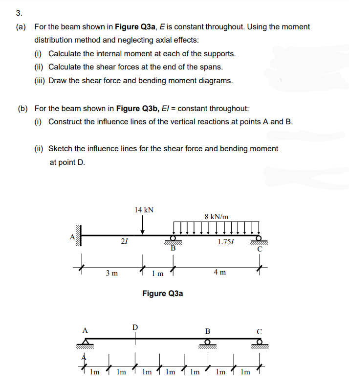
Transcribed Image Text:3.
(a) For the beam shown in Figure Q3a, E is constant throughout. Using the moment
distribution method and neglecting axial effects:
(i) Calculate the internal moment at each of the supports.
(ii) Calculate the shear forces at the end of the spans.
(iii) Draw the shear force and bending moment diagrams.
(b) For the beam shown in Figure Q3b, El = constant throughout:
(i) Construct the influence lines of the vertical reactions at points A and B.
(ii) Sketch the influence lines for the shear force and bending moment
at point D.
14 kN
8 kN/m
21
1.751
3 m
1 m
4 m
Figure Q3a
D
A
B
lm
Im
Im
1m
lm
1m
lm
Expert Solution
This question has been solved!
Explore an expertly crafted, step-by-step solution for a thorough understanding of key concepts.

Step by step
Solved in 7 steps with 7 images

Knowledge Booster


Learn more about
Need a deep-dive on the concept behind this application? Look no further. Learn more about this topic, civil-engineering and related others by exploring similar questions and additional content below.Recommended textbooks for you