What are influence lines?
The graphs that show the variation of a function at a specific point on a beam or truss due to a unit load placed at any point along the structure are known as influence lines in engineering. Some common functions that are studied with influence lines are shear, moment, and deflection. In designing beams and trusses, it is important to use influence lines in structures where loads would move along their span such as bridges, crane rails, conveyor belts, floor girders, etc. The influence lines help to study where a load will create the maximum effect for any of the functions.
Structure
A structure mainly comprises multiple members or bodies connected and behaves as a single rigid body. Certain degrees of freedom of each member is restricted in a structure, which is formed to support and bear external loads. Loads acting on the structure can be live loads, that change frequently with time, a unit load, shear forces, dead loads, and static loads. Under the influence of such loads, each member undergoes deformations and develops internal stresses. Determination of these internal stresses, deformations, and reaction forces are very crucial to estimate the permissible loads, under which these structures can perform safely.
Structural analysis is a methodology in structural engineering that specially deals with analyzing these structures and their members, and also estimates the safe loading conditions, along with the determination of internal stresses, reaction forces, moments, and strains. In structural analysis, conventional methods and equations of statics are applied. In statics, the members are assumed to be in static equilibrium under the action of external forces.
Due to the material property and nature of loads, the resulting moments, shear forces, deflections, and reactions induced due to the external loading conditions, vary throughout the length of the members. Hence, it is very important to know the magnitudes of these parameters at any point of the members to determine the critical areas. It can be determined by drawing influence lines, which are straight lines that show the variation of shear forces, bending moments, deflections, and reactions throughout the member length when concentrated unit loads shift through the member length. Influence lines are extremely necessary for designing structures that resist live loads.
Statically indeterminate and determinate structures
The very first step in structural analysis is to determine the external reactions. The degree of complexity in determining the reactions depends upon whether the structures being analyzed are statically determinate structures or statically indeterminate structures.
Statically determinate structure
A structure can be termed as a statically determinate structure if it is stable, and its reactions can be determined easily from the equilibrium equations. The three equilibrium equations are,
, where represents the algebraic sum of all the forces along the vertical direction.
, where represents the algebraic sum of all the forces along the horizontal direction.
, where represents the algebraic sum of all the bending moments.
Statically indeterminate structure
A structure is termed as a statically indeterminate structure if its associated reactions cannot be determined merely by using the three equilibrium equations. In such a case, an additional equation, known as the compatibility equation, is needed to determine the reactions.
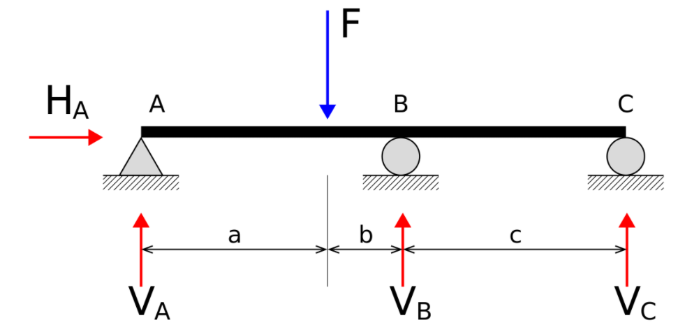
The above figure shows a statically indeterminate beam. Here, the beam is supported on two roller supports, point B and point C; and one fixed support, point A. This condition induces four unknown reactions. These four unknown reactions cannot be determined by three equilibrium equations.
Steps to draw influence lines
For static loading conditions, the variation of shear forces and bending moments can be determined by drawing shear force diagrams (SFDs) and bending moment diagrams (BMDs). These diagrams also aid in determining the maximum shear force and bending moment associated with the member.
However, when the load is not fixed, it changes continuously with time. For instance, live loads, under such conditions, the SFDs and BMDs cannot predict the variations. Hence, influence lines become an important tool to estimate the variations.
To draw influence lines, the following basic steps are followed,
- A unit load of unit magnitude is considered for the purpose.
- A point of interest is chosen where the estimation of shear force, bending moment, and deflection is required.
- The unit load is placed at various locations of the member, and principles of statics are applied to determine the reaction forces, shear forces, bending moments, and deflections. The required parameters for the given unit load are obtained by multiplying the ordinate of the influence line diagram by the chosen unit load. This can be well understood by following the Muller Breslau principle.
- The results are plotted in a graphical manner such as (Shear force diagram) SFDs and (Bending moment diagram) BMDs, and the maximum values and variations are analyzed.
- Influence lines are generally straight for statically determinate structures.
Muller Breslau principle
The Muller Breslau principle establishes a relationship between the ordinate of influence line and the ordinate of the elastic curve. It simply states that the ordinate of the influence line for a particular bending moment, reaction, shear force, and deflection is given by the ordinate of the elastic curve due to a unit deflection undergone by the member along the direction of the induced reaction.
The procedure to apply the Muller Breslau principle is similar to the virtual work principle in mechanics.
Following are the procedures to apply the Muller Breslau principle for a simply supported beam,
- When the influence line for a vertical reaction is needed, the support that induces the reaction is removed and the beam is assumed to freely undergo displacement under the reaction and rotate about the other support.
- If the influence line for a moment is needed, the point of application of the moment is considered to be hinged and the sides of the beam can rotate freely about the supports.
- Similarly, if the influence line for a shear force is required, the point where the sheer force is acting is assumed to undergo shear displacements, with the two sides of the beam being able to rotate about their supports.
- The portion of the beam which is not assumed to undergo displacements is considered to have infinite rigidity.
- One unit of displacement is applied to the beam under the influence of shear forces, reactions, bending moments, and deformations.
Context and Applications
The topic finds its presence in various undergraduate and postgraduate degree courses of,
- Bachelors in Technology (Civil engineering)
- Bachelors in Technology (Mechanical engineering)
- Masters in Technology (Civil engineering)
- Masters in Technology (Mechanical engineering)
- Bachelors in Science (Physics)
- Bachelors in Applied Science
Practice Problems
Q1) Which of the following loads is assumed in developing an influence line diagram?
- live load
- dead load
- static load
- unit load
Correct option: d
Explanation: To estimate the variation due to living loads, an influence line diagram is drawn. In the influence line diagram, a unit load is assumed in place of the given external loading.
Q2) Which of the following is true for Muller Breslau principle?
- Its application is similar to the virtual work principle.
- The point of application of moment is assumed to be a hinged joined.
- It assumes unit displacements.
- All of these.
Correct option: d
Explanation: The Muller Breslau principle assumes that the member undergoes unit displacements under the influence of external loads. The analysis is similar to the virtual work principle in mechanics. The point of interest in the member under the influence of a bending moment is assumed to be a hinged joint that is free to rotate.
Q3) Which of the following structural conditions results in a straight line in influence line diagram?
- When the structure statically indeterminate
- When the structure is statically determinate
- When the structure is stable
- When the structure is unstable
Correct option: b
Explanation: For a statically determinate structure, the influence line is a straight line.
Q4) Which of the following loading condition needs an influence line diagram for analysis?
- When the load in the member is static.
- When the load in the member is gradually improving.
- When the load in the member is a live load or a moving load.
- None of these
Correct option: c
Explanation: When the members are under the application of live loads, traditional SFDs and BMDs cannot be used to estimate the variations. Under these circumstances, an influence line diagram needs to be drawn.
Q5) When the number of reactions can be easily determined by number of equilibrium equations, which of the following holds true for a beam?
- The beam is statically indeterminate.
- The beam is a stable beam.
- The beam is statically determinate.
- The beam is internally stable.
Correct option: c
Explanation: When for a beam, the number of reactions can be easily estimated by the number of equilibrium equations, the beam is said to be a statically determinate beam.
Want more help with your civil engineering homework?
*Response times may vary by subject and question complexity. Median response time is 34 minutes for paid subscribers and may be longer for promotional offers.
Search. Solve. Succeed!
Study smarter access to millions of step-by step textbook solutions, our Q&A library, and AI powered Math Solver. Plus, you get 30 questions to ask an expert each month.
Influence Lines Homework Questions from Fellow Students
Browse our recently answered Influence Lines homework questions.
Search. Solve. Succeed!
Study smarter access to millions of step-by step textbook solutions, our Q&A library, and AI powered Math Solver. Plus, you get 30 questions to ask an expert each month.