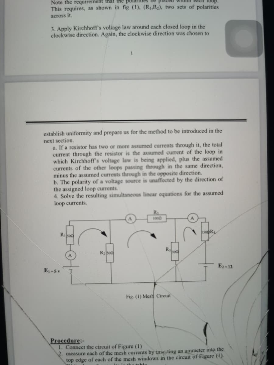
3. Apply Kirchhoff's voltage law around each closed loop in the clockwise direction. Again, the clockwise direction was chosen to establish uniformity and prepare us for the method to be introduced in the next section. a. If a resistor has two or more assumed currents through it, the total current through the resistor is the assumed current of the loop in which Kirchhoff's voltage law is being applied, plus the assumed currents of the other loops passing through in the same direction, minus the assumed currents through in the opposite direction. b. The polarity of a voltage source is unaffected by the direction of the assigned loop currents. 4. Solve the resulting simultaneous linear equations for the assumed loop currents. sopR Rilsod Rsed E2-12 E1-5 v Fig. (1) Mesh Circuit
3. Apply Kirchhoff's voltage law around each closed loop in the clockwise direction. Again, the clockwise direction was chosen to establish uniformity and prepare us for the method to be introduced in the next section. a. If a resistor has two or more assumed currents through it, the total current through the resistor is the assumed current of the loop in which Kirchhoff's voltage law is being applied, plus the assumed currents of the other loops passing through in the same direction, minus the assumed currents through in the opposite direction. b. The polarity of a voltage source is unaffected by the direction of the assigned loop currents. 4. Solve the resulting simultaneous linear equations for the assumed loop currents. sopR Rilsod Rsed E2-12 E1-5 v Fig. (1) Mesh Circuit

Power System Analysis and Design (MindTap Course List)
6th Edition
ISBN:9781305632134
Author:J. Duncan Glover, Thomas Overbye, Mulukutla S. Sarma
Publisher:J. Duncan Glover, Thomas Overbye, Mulukutla S. Sarma
Chapter6: Power Flows
Section: Chapter Questions
Problem 6.27P

Related questions
Question
Transcribed Image Text:Note the requirement that the po
This requires, as shown in fig (1), (R1,R3), two sets of polarities
across it.
3. Apply Kirchhoff's voliage law around each closed loop in the
clockwise direction. Again, the clockwise direction was chosen to
establish uniformity and prepare us for the method to be introduced in the
next section.
a. If a resistor has two or more assumed currents through it, the total
current through the resistor is the assumed current of the loop in
which Kirchhoff's voltage law is being applied, plus the assumed
currents of the other loops passing through in the same direction,
minus the assumed currents through in the opposite direction.
b. The polarity of a voltage source is unaffected by the direction of
the assigned loop currents.
4. Solve the resulting simultancous linear equations for the assumed
loop currents.
Rilsod
Rsoa
E2-12
E1-5 v
Fig. (1) Mesh Circuit
Procedure:-
1. Connect the circuit of Figure (1)
2. measure each of the mesh currents by inscrting an ammeter into the
top edge of each of the mesh windows in the circuit of Figure (4).
a table
Expert Solution
This question has been solved!
Explore an expertly crafted, step-by-step solution for a thorough understanding of key concepts.

Step by step
Solved in 4 steps

Knowledge Booster


Learn more about
Need a deep-dive on the concept behind this application? Look no further. Learn more about this topic, electrical-engineering and related others by exploring similar questions and additional content below.Recommended textbooks for you
Power System Analysis and Design (MindTap Course …
Electrical Engineering
ISBN:
9781305632134
Author:
J. Duncan Glover, Thomas Overbye, Mulukutla S. Sarma
Publisher:
Cengage Learning
Power System Analysis and Design (MindTap Course …
Electrical Engineering
ISBN:
9781305632134
Author:
J. Duncan Glover, Thomas Overbye, Mulukutla S. Sarma
Publisher:
Cengage Learning