3. Consider the following VHDL code. library jeee; use ieee.std_logic_1164.all; entity pylsedet is port( signal çlk, reset, pulsRin: in std logic; signal pylsefaltt: out stLtegis ); end pulsedet; architecture behavior of pulsedet is signal dffouti std logic vestor (2 downto 0); begin dffs: process (clk,reset) begin if (reset = '1') then dffout <= "000"; elsif (sikevent and slk='1') then dffout 12) <= dffout (1); dffout (1) <= dffout(0); dffout (0) <= pulse in; end if; end process; pulseQut <= dffout(2) and not dffout(1); end behavior; %3D Draw a diagram of logic (combinatorial gates VHDL code. and flip-flops) that implements the
3. Consider the following VHDL code. library jeee; use ieee.std_logic_1164.all; entity pylsedet is port( signal çlk, reset, pulsRin: in std logic; signal pylsefaltt: out stLtegis ); end pulsedet; architecture behavior of pulsedet is signal dffouti std logic vestor (2 downto 0); begin dffs: process (clk,reset) begin if (reset = '1') then dffout <= "000"; elsif (sikevent and slk='1') then dffout 12) <= dffout (1); dffout (1) <= dffout(0); dffout (0) <= pulse in; end if; end process; pulseQut <= dffout(2) and not dffout(1); end behavior; %3D Draw a diagram of logic (combinatorial gates VHDL code. and flip-flops) that implements the

Introductory Circuit Analysis (13th Edition)
13th Edition
ISBN:9780133923605
Author:Robert L. Boylestad
Publisher:Robert L. Boylestad
Chapter1: Introduction
Section: Chapter Questions
Problem 1P: Visit your local library (at school or home) and describe the extent to which it provides literature...

Related questions
Question
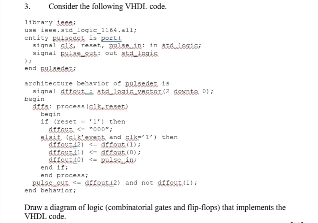
Transcribed Image Text:3.
Consider the following VHDL code.
library jeee;
use ieee.std_logic_1164.all;
entity pulsedet is port(
signal çlk, reset, pulsRin: in std logic;
signal pulsRut: out stdlegis
) ;
end pulsedet;
architecture behavior of pulsedet is
signal dffout_i st&legis vestor (2 dewnte 0);
begin
d££s: process (cikateset)
begin
if (reset = '1') then
dffout <= "000";
elsif (sikievent and slk='1') then
dffout (2) <= dffout(1);
dffout (1) <= dffout(0);
d££QutL0) <= pulsein;
end if;
end process;
pulseQut <= dffout_(2) and not dfEout (1);
end behavior;
Draw a diagram of logic (combinatorial gates and flip-flops) that implements the
VHDL code.
Expert Solution
This question has been solved!
Explore an expertly crafted, step-by-step solution for a thorough understanding of key concepts.

This is a popular solution!

Trending now
This is a popular solution!

Step by step
Solved in 2 steps with 2 images

Knowledge Booster


Learn more about
Need a deep-dive on the concept behind this application? Look no further. Learn more about this topic, electrical-engineering and related others by exploring similar questions and additional content below.Recommended textbooks for you
Introductory Circuit Analysis (13th Edition)
Electrical Engineering
ISBN:
9780133923605
Author:
Robert L. Boylestad
Publisher:
PEARSON

Delmar's Standard Textbook Of Electricity
Electrical Engineering
ISBN:
9781337900348
Author:
Stephen L. Herman
Publisher:
Cengage Learning

Programmable Logic Controllers
Electrical Engineering
ISBN:
9780073373843
Author:
Frank D. Petruzella
Publisher:
McGraw-Hill Education
Introductory Circuit Analysis (13th Edition)
Electrical Engineering
ISBN:
9780133923605
Author:
Robert L. Boylestad
Publisher:
PEARSON
Delmar's Standard Textbook Of Electricity
Electrical Engineering
ISBN:
9781337900348
Author:
Stephen L. Herman
Publisher:
Cengage Learning
Programmable Logic Controllers
Electrical Engineering
ISBN:
9780073373843
Author:
Frank D. Petruzella
Publisher:
McGraw-Hill Education

Fundamentals of Electric Circuits
Electrical Engineering
ISBN:
9780078028229
Author:
Charles K Alexander, Matthew Sadiku
Publisher:
McGraw-Hill Education

Electric Circuits. (11th Edition)
Electrical Engineering
ISBN:
9780134746968
Author:
James W. Nilsson, Susan Riedel
Publisher:
PEARSON

Engineering Electromagnetics
Electrical Engineering
ISBN:
9780078028151
Author:
Hayt, William H. (william Hart), Jr, BUCK, John A.
Publisher:
Mcgraw-hill Education,