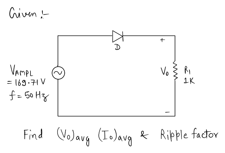
3. For the half-wave rectifier given in the figure below, find the average values of the output voltage and current, and the ripple factor of the output voltage.
3. For the half-wave rectifier given in the figure below, find the average values of the output voltage and current, and the ripple factor of the output voltage.

Electricity for Refrigeration, Heating, and Air Conditioning (MindTap Course List)
10th Edition
ISBN:9781337399128
Author:Russell E. Smith
Publisher:Russell E. Smith
Chapter12: Electronic Control Devices
Section: Chapter Questions
Problem 4RQ: What is the difference between a diode and rectifier?

Related questions
Question
3. For the half-wave rectifier given in the figure below, find the average values of
the output voltage and current, and the ripple factor of the output voltage.
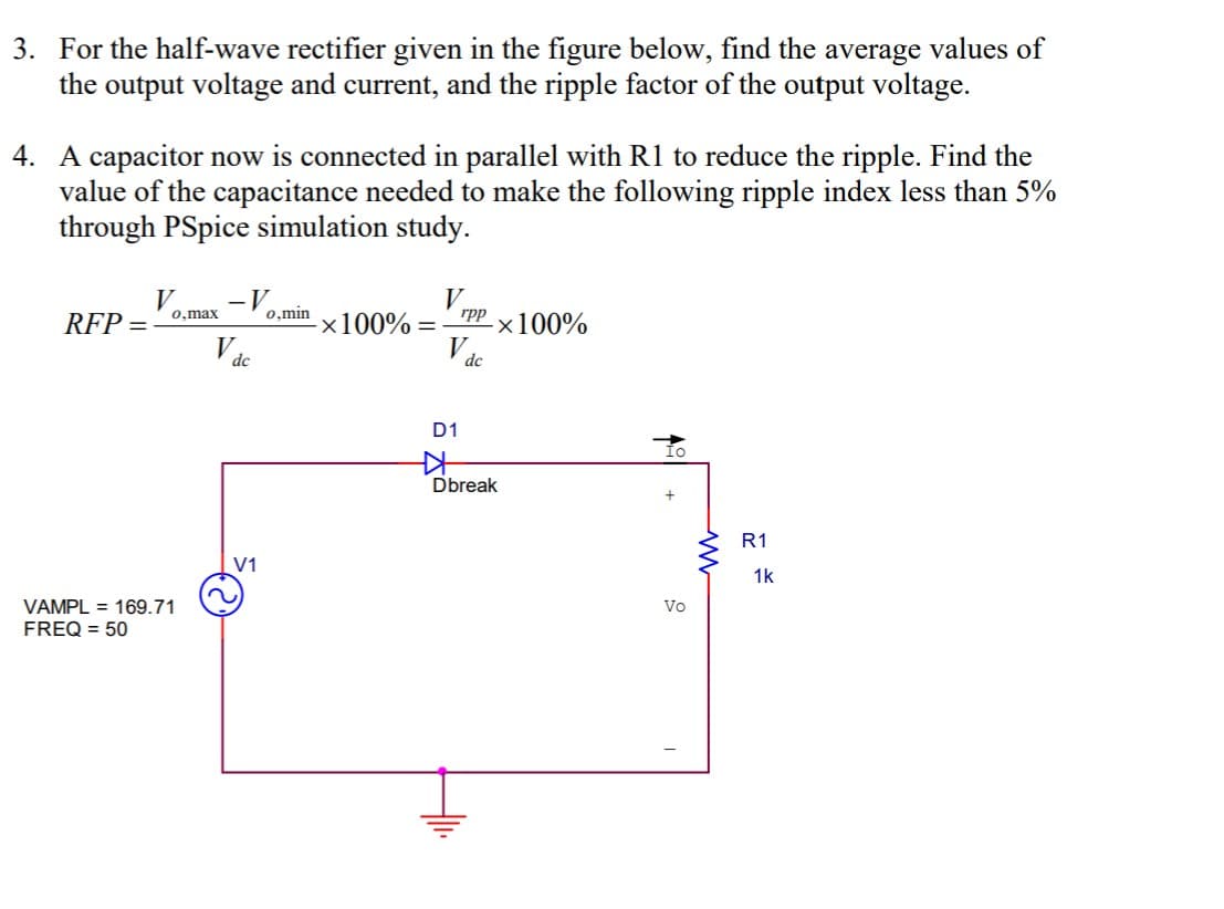
Transcribed Image Text:3. For the half-wave rectifier given in the figure below, find the average values of
the output voltage and current, and the ripple factor of the output voltage.
4. A capacitor now is connected in parallel with R1 to reduce the ripple. Find the
value of the capacitance needed to make the following ripple index less than 5%
through PSpice simulation study.
V
RFP =
-V
0,min
0,max
rpp
x100% =
-×100%
dc
dc
D1
Dbreak
R1
V1
1k
Vo
VAMPL = 169.71
FREQ = 50
Expert Solution
Step 1

Trending now
This is a popular solution!

Step by step
Solved in 2 steps with 2 images

Knowledge Booster


Learn more about
Need a deep-dive on the concept behind this application? Look no further. Learn more about this topic, electrical-engineering and related others by exploring similar questions and additional content below.Recommended textbooks for you
Electricity for Refrigeration, Heating, and Air C…
Mechanical Engineering
ISBN:
9781337399128
Author:
Russell E. Smith
Publisher:
Cengage Learning
Electricity for Refrigeration, Heating, and Air C…
Mechanical Engineering
ISBN:
9781337399128
Author:
Russell E. Smith
Publisher:
Cengage Learning