3. Repeat Problem 1, but this time both resistors R₁ and R₂ are implemented using the three terminals of a 10k pot so that R₁ and R₂ are both variable such that 0 ≤ R₂ ≤ 10kN and R₁ + R₂ = 10k. Find the range of values for R₂ that will cause the output voltage to vary over the range 1.5V ≤ V₂ ≤ 5.0V. Show how you arrived at this range.
3. Repeat Problem 1, but this time both resistors R₁ and R₂ are implemented using the three terminals of a 10k pot so that R₁ and R₂ are both variable such that 0 ≤ R₂ ≤ 10kN and R₁ + R₂ = 10k. Find the range of values for R₂ that will cause the output voltage to vary over the range 1.5V ≤ V₂ ≤ 5.0V. Show how you arrived at this range.

Introductory Circuit Analysis (13th Edition)
13th Edition
ISBN:9780133923605
Author:Robert L. Boylestad
Publisher:Robert L. Boylestad
Chapter1: Introduction
Section: Chapter Questions
Problem 1P: Visit your local library (at school or home) and describe the extent to which it provides literature...

Related questions
Question
v1= 9V
Transcribed Image Text:V₁
+
I
www
R₁
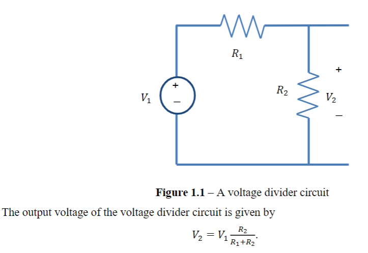
The output voltage of the voltage divider circuit is given by
R₂
V₂ = V₁R₁+R₂°
R2
V₂
Figure 1.1 - A voltage divider circuit
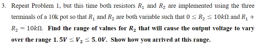
Transcribed Image Text:3. Repeat Problem 1, but this time both resistors R₁ and R₂ are implemented using the three
terminals of a 10k pot so that R₁ and R₂ are both variable such that 0 ≤ R₂ ≤ 10kN and R₁ +
R₂ = 10k№. Find the range of values for R₂ that will cause the output voltage to vary
over the range 1. 5V ≤ V₂ ≤ 5. 0OV. Show how you arrived at this range.
2
Expert Solution
This question has been solved!
Explore an expertly crafted, step-by-step solution for a thorough understanding of key concepts.

Step by step
Solved in 2 steps with 2 images

Knowledge Booster


Learn more about
Need a deep-dive on the concept behind this application? Look no further. Learn more about this topic, electrical-engineering and related others by exploring similar questions and additional content below.Recommended textbooks for you
Introductory Circuit Analysis (13th Edition)
Electrical Engineering
ISBN:
9780133923605
Author:
Robert L. Boylestad
Publisher:
PEARSON

Delmar's Standard Textbook Of Electricity
Electrical Engineering
ISBN:
9781337900348
Author:
Stephen L. Herman
Publisher:
Cengage Learning

Programmable Logic Controllers
Electrical Engineering
ISBN:
9780073373843
Author:
Frank D. Petruzella
Publisher:
McGraw-Hill Education
Introductory Circuit Analysis (13th Edition)
Electrical Engineering
ISBN:
9780133923605
Author:
Robert L. Boylestad
Publisher:
PEARSON
Delmar's Standard Textbook Of Electricity
Electrical Engineering
ISBN:
9781337900348
Author:
Stephen L. Herman
Publisher:
Cengage Learning
Programmable Logic Controllers
Electrical Engineering
ISBN:
9780073373843
Author:
Frank D. Petruzella
Publisher:
McGraw-Hill Education

Fundamentals of Electric Circuits
Electrical Engineering
ISBN:
9780078028229
Author:
Charles K Alexander, Matthew Sadiku
Publisher:
McGraw-Hill Education

Electric Circuits. (11th Edition)
Electrical Engineering
ISBN:
9780134746968
Author:
James W. Nilsson, Susan Riedel
Publisher:
PEARSON

Engineering Electromagnetics
Electrical Engineering
ISBN:
9780078028151
Author:
Hayt, William H. (william Hart), Jr, BUCK, John A.
Publisher:
Mcgraw-hill Education,