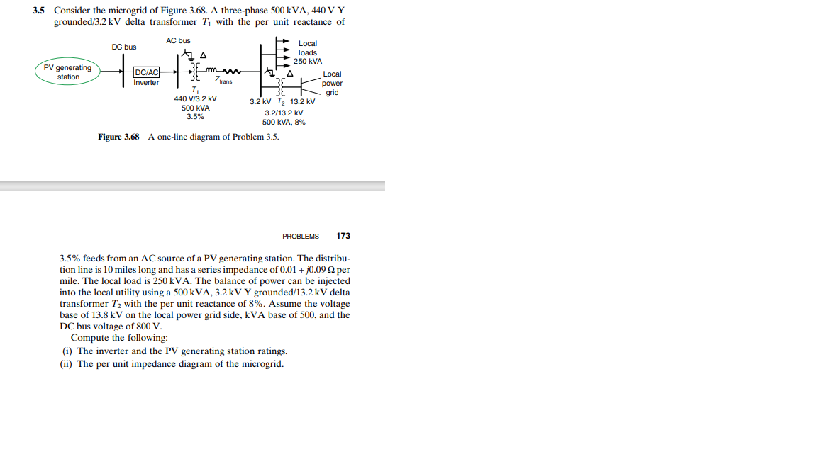
3.5 Consider the microgrid of Figure 3.68. A three-phase 500 kVA, 440 V Y grounded/3.2 kV delta transformer T, with the per unit reactance of AC bus Local loads 250 kVA DC bus PV generating station DC/AC Inverter m Zyans Local power grid 3.2 kv T2 13.2 KV 440 V/3.2 kV 500 kVA 3.5% 3.2/13.2 kV 500 KVA, 8% Figure 3.68 A one-line diagram of Problem 3.5. PROBLEMS 173 3.5% feeds from an AC source of a PV generating station. The distribu- tion line is 10 miles long and has a series impedance of 0.01 + j0.09 2 per mile. The local load is 250 kVA. The balance of power can be injected into the local utility using a 500 kVA, 3.2 kV Y grounded/13.2 kV delta transformer T2 with the per unit reactance of 8%. Assume the voltage base of 13.8 kV on the local power grid side, kVA base of 500, and the DC bus voltage of 800 V. Compute the following: (i) The inverter and the PV generating station ratings. (ii) The per unit impedance diagram of the microgrid.
3.5 Consider the microgrid of Figure 3.68. A three-phase 500 kVA, 440 V Y grounded/3.2 kV delta transformer T, with the per unit reactance of AC bus Local loads 250 kVA DC bus PV generating station DC/AC Inverter m Zyans Local power grid 3.2 kv T2 13.2 KV 440 V/3.2 kV 500 kVA 3.5% 3.2/13.2 kV 500 KVA, 8% Figure 3.68 A one-line diagram of Problem 3.5. PROBLEMS 173 3.5% feeds from an AC source of a PV generating station. The distribu- tion line is 10 miles long and has a series impedance of 0.01 + j0.09 2 per mile. The local load is 250 kVA. The balance of power can be injected into the local utility using a 500 kVA, 3.2 kV Y grounded/13.2 kV delta transformer T2 with the per unit reactance of 8%. Assume the voltage base of 13.8 kV on the local power grid side, kVA base of 500, and the DC bus voltage of 800 V. Compute the following: (i) The inverter and the PV generating station ratings. (ii) The per unit impedance diagram of the microgrid.

Power System Analysis and Design (MindTap Course List)
6th Edition
ISBN:9781305632134
Author:J. Duncan Glover, Thomas Overbye, Mulukutla S. Sarma
Publisher:J. Duncan Glover, Thomas Overbye, Mulukutla S. Sarma
Chapter3: Power Transformers
Section: Chapter Questions
Problem 3.25P: Consider a single-phase electric system shown in Figure 3.33. Transformers are rated as follows:...

Related questions
Question
Qusation as per attaced picture
Transcribed Image Text:Consider the microgrid of Figure 3.68. A three-phase 500 kVA, 440 V Y
grounded/3.2 kV delta transformer T1 with the per unit reactance of
3.5
AC bus
Local
DC bus
loads
250 kVA
PV generating
station
DC/ACH
Local
Zrans
Inverter
power
T,
440 V/3.2 kV
grid
3.2 kV T, 13.2 kV
500 kVA
3.5%
3.2/13.2 kV
500 kVA, 8%
Figure 3.68 A one-line diagram of Problem 3.5.
PROBLEMS
173
3.5% feeds from an AC source of a PV generating station. The distribu-
tion line is 10 miles long and has a series impedance of 0.01 + j0.09 2 per
mile. The local load is 250 kVA. The balance of power can be injected
into the local utility using a 500 kVA, 3.2 kV Y grounded/13.2 kV delta
transformer T2 with the per unit reactance of 8%. Assume the voltage
base of 13.8 kV on the local power grid side, kVA base of 500, and the
DC bus voltage of 800 V.
Compute the following:
(i) The inverter and the PV generating station ratings.
(ii) The per unit impedance diagram of the microgrid.
Expert Solution
This question has been solved!
Explore an expertly crafted, step-by-step solution for a thorough understanding of key concepts.

This is a popular solution!

Trending now
This is a popular solution!

Step by step
Solved in 5 steps with 3 images

Recommended textbooks for you
Power System Analysis and Design (MindTap Course …
Electrical Engineering
ISBN:
9781305632134
Author:
J. Duncan Glover, Thomas Overbye, Mulukutla S. Sarma
Publisher:
Cengage Learning
Power System Analysis and Design (MindTap Course …
Electrical Engineering
ISBN:
9781305632134
Author:
J. Duncan Glover, Thomas Overbye, Mulukutla S. Sarma
Publisher:
Cengage Learning