4. A steel bar in Fig. 2 of length L= 2.0 m is compressed by axial load at the midpoint of one side of the cross section. Assuming E= 210 GPa and both ends of the bar are pinned, calculate i. the maximum deflection ii. maximum bending moment. P=60 kN 50 mm 50 mm Figure 1
Q: A simply supported beam with span of 8 m is subjected to a counterclockwise moment at the left…
A: Given Data The length of the beam is:L=8m The yield strength of the steel beam is:Fy=248 MPa The…
Q: H.W 3_ Two aluminum alloy plates (2) are attached to the sides of a wooden beam (1) as shown in…
A:
Q: A I-meter-long, simply supported copper beam (E= 117 GPa) carries uniformly distributed load q. The…
A:
Q: 3) On a structural steel I profile beam a distributed load and M moment is applied as shown in the…
A: Youngs modulus E = 200 GPa Length, L = 1 m Moment, M = 245 N-m Cross section dimensions h = 145 mm b…
Q: A simply supported beam of length 30-in diamater 2-in is supported at A and D, subject to load P at…
A:
Q: In the figure, aluminum [E = 72 GPa] links (1) and (2) support rigid beam ABC. Link (1) has a…
A:
Q: Question Two For the shown simply supported beam, a deflection of 1.5 mm is developed in the beam at…
A:
Q: A cantilever beam AB with rectangle cross section has a longitudinal hole drilled throughout its…
A:
Q: 30. A bar of circular cross section is clamped at ends P and Q as shown in the figure. A torsional…
A: Consider the torque at end P is T1 and the torque at the end Q is T2.
Q: a beam AD with a length of 5m is subjected to point loads of 8kN and 6kN at B and C as shown in…
A:
Q: The slope at end of the point A (ii) The deflection at point C
A:
Q: A PB y Pc W1 В W2 H A B C L1 L2
A:
Q: In the figure, aluminum [E = 60 GPa] links (1) and (2) support rigid beam ABC. Link (1) has a…
A:
Q: (b) A simple beam ABCD with a uniformly loading and a single load at point C is shown in Figure…
A: (i) Draw the free-body diagram of the given beam.
Q: In the figure, aluminum [E = 60 GPa] links (1) and (2) support rigid beam ABC. Link (1) has a…
A: Data given - a = 1380 mm, b = 760 mm, L₁= 2570 mm, and L₂ = 4650 mm. P = 32 kN A2 = 430 mm2 A1 =…
Q: Axial Loadings Consider the figure shown. A rigid beam is pinned at one end and supported by two…
A: For solution refer below images.
Q: Q2: For the beam shown in Figure (2), determine transverse shear stresses at points E, F and G on…
A: Find the transverse shear stress .
Q: The figure shows a cantilever consisting of steel angles size 100 x 100 x 12 mm mounted back to…
A: given data; ⇒w=1KN/mF=2.5KN⇒OA=2m⇒OB=3m⇒AB=1m
Q: Q2: For the beam shown in Figure (2), determine transverse shear stresses E, F and G on the cross…
A: GivenP=100kNINA=470016 mm4
Q: QUESTION 4 Solve the problem by the moment-area method. The beam has constant flexural rigidity EI.…
A: To find : The deflection δAand δB at point B and C . Given : The moment of inertia is I=18.1×10⁶…
Q: 2 kip/ft 6 in 10 in B. +40 kip 16 in D. 16 in 5t 5 ft 10 ft The simply-supported beam-column above…
A:
Q: (a) Taking into account only the effect of normal stress, determine the strain energy of prismatic…
A:
Q: The cross-section of beam shown in Figure Q2 (centroid in red) is subjected to pure bending. Taking…
A:
Q: A curved frame ABC is fixed at one end and subjected to a concentrated load P, as shown in Figure.…
A: →For section AB(0≤x≤L):-Mx=PxMx=0=MA=0Mx=L=MB=PL →For section BC:- Equation of moment at an angle…
Q: the deflection at C to be zero , the ratio P/F
A: Given; A horizontal bar with a constant cross-section is subjected to loadingas given in…
Q: 9.3-2 A l-meter-long, simply supported copper beam (E = 117 GPa) carries uniformly distributed load…
A: given data; young modulus(E)=117GPa =117*103MPalength of beam(L)=1m…
Q: Q1: The horizontal rigid beam ABCD is supported by vertical bars BE and CF and is loaded by vertical…
A:
Q: Consider the beam shown in sketch below, hinge supported at point A and roller supported at point D.…
A: Considering the cross-section of the beam The web is denoted as 1 and flange is denoted as 2
Q: A beam ABCD rests on simple supports at B and C. The beam has a slight initial curvature so that end…
A:
Q: 4. A cantilever beam with cross section shown below and span of 3 m is subjected to concentrated…
A: Given Data: The span of the beam is L = 3 m. The concentrated load acting on the beam is P at its…
Q: Problem 5 A 1/4-in-thick beam OAB is fixed to the wall at one end and supported by a 1/2-in-…
A: The beam which is rigidly held at one end and free to oscillate or deflect at the other end is…
Q: A simply supported beam is loaded as shown in the figure. Determine the slope and deflection at the…
A:
Q: Ahorizontal beam AB with cross-sectional dimensions 4 ft -5 ft Ab # 075 in.)X h#8.0 in. is supported…
A:
Q: A flanged wooden shape is used to support the loads shown on the beam. The dimensions of the shape…
A:
Q: The composite beam shown in the Figure below is formed of a wood beam and a steel reinforcing plate.…
A:
Q: The iron beam with E=120 GPa as shown in Figure 2, is subjected to a moment of 600 N.m. 25 mm 150 mm…
A:
Q: In the figure, aluminum [E = 75 GPa] links (1) and (2) support rigid beam ABC. Link (1) has a…
A:
Q: Q/ For the beam shown in the figure below, find deflection and rotation at point B. EI=12000 kN.m?.…
A:
Q: Question Four A beam of the cross section that is shown in Figure a was supported by two rigid…
A: given data: maximum allowable tensile stress σ=50MPa own weight of beam(w)=1.5KN/mweight of beam…
Q: In the figure, aluminum [E = 75 GPa] links (1) and (2) support rigid beam ABC. Link (1) has a…
A: Consider a bar having cross-sectional area A,Length L and Young's Modulus E is subjected to axial…
Q: A beam supported by two identical springs at points A and B (see figure). Given that flexural of…
A:
Q: The beam AB, shown in Figure 1a, with length L = 4.5 m is subjected to a uniform distributed load w…
A: A beam is defined as a structural member subjected to transverse shear load during its…
Q: The iron beam with E=120 GPa as shown in Figure 2, is subjected to a moment of 600 N.m. 25 mm 150 mm…
A:
Q: Q.1) For the figure shown, have the following information: (2) Link (1) made Link (2) made of…
A:
Q: Aluminum beam AB (E=10x106 psi) is fixed to a wall at point A as shown. Magnesium rod CD (a = 14.5 x…
A:
Q: Calculate the vertical shear stress (N / cm2) at point A in the critical section of the beam below…
A: Please refer to the detailed attached solution:
provide full calculation
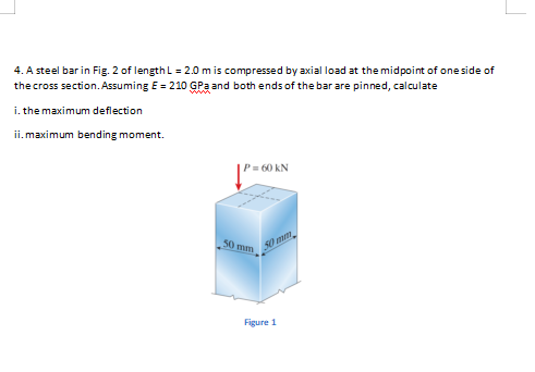
Step by step
Solved in 3 steps with 4 images
- A horizontal beam AB is pin-supported at end A and carries a clockwise moment M at joint B, as shown in the figure. The beam is also supported at C by a pinned-end column of length L: the column is restrained laterally at 0.6Z, from the base at D. Assume the column can only buckle in the plane of the frame. The column is a solid steel bar (E = 200 GPa) of square cross section having length L = 2.4 m and side dimensions h = 70 mm. Let dimensions d = LI2. Based upon the critical load of the column, determine the allowable moment M if the factor of safety with respect to buckling is n = 2.0.A thin, high-strength steel rule (E = 30 x 10ft psi) having a thickness t = 0.175 in. and length L = 48 in. is bent by couples Mcinto a circular arc subtending a central angle a = 40° (sec figure), What is the maximum bending stress emax. in the rule? By what percent docs the stress increase or decrease if the central angle is increased by 10%? What percent increase or decrease in rule thickness will result in the maximum stress reaching the allowable value of 42 ksi?An S6 × 12.5 steel cantilever beam AB is supported by a steel tic rod at B as shown. The tie rod is just taut when a roller support is added at Cat a distance s to the left of £, then the distributed load q is applied to beam segment AC, Assume E = 30 × 106 psi and neglect the self-weight of the beam and tie rod. Sec Table F-2(a) in Appendix F for the properties of the S-shape beam. (a) What value of uniform load q will, if exceeded, result in buckling of the tie rod if L1, =6 ft, s = 2 ft, H = 3 ft, and d = 0.25 in.? (b) What minimum beam moment of inertia ibis required to prevent buckling of the tie rod if q = 200 lb/ft, L1, = 6 ft, H = 3 ft, d = 0.25 in., and s = 2 ft? (c) For what distance s will the tic rod be just on the verge of buckling if q = 200 lb/ft, L1= 6 ft, M = 3 ft, and d = 0.25 in.?
- A fiberglass bracket A BCD with a solid circular cross section has the shape and dimensions shown in the figure, A vertical load P = 40 N acts at the free end D. Determine the minimum permissible diameter ^nwi °f tnc bracket if the allowable bending stress in the material is 30 MPa and/? = 37 mm. Note: Disregard the weight of the bracket itself. If d = 10 nun, b = 37 mm, and= 30 MPa, what is the maximum value of load P if vertical load P at D is replaced with horizontal loads P at B and D (see figure part b)?A wood beam with cross-sectional dimensions 200 mm x 300 mm is reinforced on its sides by steel plates 12 mm thick (see figure). The moduli of elasticity for the steel and wood are E±= 190 GPa and Ew= 11 GPa, respectively. Also, the corresponding allowable stresses are eS= 110 MPa and ew = 7.5 MPa, (a) Calculate the maximum permissible bending moment Mmaxwhen the beam is bent about the- axis. Repeat part (a) if the beam is now bent about its y axis. Find the required thickness of the steel plates on the beam bent about the y axis so that Mmaxis the same for both beam orientations.An aluminum bar having a rectangular cross section (2.0 in. × 1.0 in.) and length L = 30 in. is compressed by axial loads that have a resultant P = 2800 lb acting at the midpoint of the long side of the cross section (sec figure). Assuming that the modulus of elasticity E is equal to 10 × 106 psi and that the ends of the bar are pinned, calculate the maximum deflection and the maximum bending moment Mmax.
- Solve the preceding problem for a box beam with dimensions h = 0.5 m, h = 0.18 m, and t = 22 mm. The yield stress of the steel is 210 MPa.A wood beam in a historic theater is reinforced with two angle sections at the outside lower corners (see figure). If the allowable stress in the wood is 12 M Pa and that in the steel is 140 M Pa, what is ratio of the maximum permissible moments for the beam before and after reinforcement with the angle sections? See Appendix F Table F-5(b) for angle section properties. Assume that ew= 12 GPa and E3=210 GPa.A cantileverbeam^Cßsupportstwo concentrated loads Ptand A, as shown in the figure. Calculate the deflections SBand 8Cat points B and C, respectively. Assume Px= 10 kN, P\ = 5 kN, L = 2.6 m, E = 200 GPa, and / = 20.1 x I0ft mm4.
- . A cantilever beam (width b = 3 in. and depth h = 6 in,) has a length L = 5 ft and is subjected to a point load P and a concentrated moment M = 20 kip-ft at end B. If normal stress trx= 0 at point C, located 0.5 in. below the top of the beam and 1 ft to the right of point Atfind point load P. Also show the complete state of plane stress on the element at point C.Beam ACE hangs from two springs, as shown in the figure. The springs have stiffnesses kxand k2and the beam has flex lira I rigidity EL (a) What is the downward displacement of point C, which is at the midpoint of the beam, when the moment M0 is applied? Data for the structure are as follows: M0= 10,0 kN m, L = 1.8 m, EI = 216 kN m2, Jt, = 250 kN/m, and k2= 160 kN/m, (b) Repeat part (a), but remove A/() and apply a uniform load q — 3.5 kN/m to the entire beam.Solve the preceding problem for a wide-flange beam with h = 404 mm, b = 140 mm, bf= 11.2 mm, and rf. = 6.99 mm.