The figure shows a cantilever consisting of steel angles size 100 x 100 x 12 mm mounted back to back. Using superposition, find the deflection at B and the maximum stress in the beam. 3 m - 2.5 kN 2 m I kN/m B A
The figure shows a cantilever consisting of steel angles size 100 x 100 x 12 mm mounted back to back. Using superposition, find the deflection at B and the maximum stress in the beam. 3 m - 2.5 kN 2 m I kN/m B A

Mechanics of Materials (MindTap Course List)
9th Edition
ISBN:9781337093347
Author:Barry J. Goodno, James M. Gere
Publisher:Barry J. Goodno, James M. Gere
Chapter9: Deflections Of Beams
Section: Chapter Questions
Problem 9.5.35P: A framework A BCD is acted on by counterclockwise moment M at A (see figure). Assume that Elis...

Related questions
Question
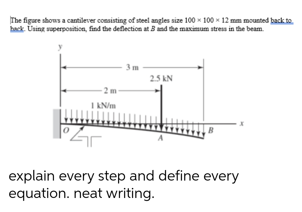
Transcribed Image Text:The figure shows a cantilever consisting of steel angles size 100 x 100 x 12 mm mounted back to
back. Using superposition, find the deflection at B and the maximum stress in the beam.
3 m
2.5 kN
- 2 m
I kN/m
explain every step and define every
equation. neat writing.
Expert Solution
This question has been solved!
Explore an expertly crafted, step-by-step solution for a thorough understanding of key concepts.

This is a popular solution!

Trending now
This is a popular solution!

Step by step
Solved in 2 steps with 3 images

Knowledge Booster


Learn more about
Need a deep-dive on the concept behind this application? Look no further. Learn more about this topic, mechanical-engineering and related others by exploring similar questions and additional content below.Recommended textbooks for you
Mechanics of Materials (MindTap Course List)
Mechanical Engineering
ISBN:
9781337093347
Author:
Barry J. Goodno, James M. Gere
Publisher:
Cengage Learning
Mechanics of Materials (MindTap Course List)
Mechanical Engineering
ISBN:
9781337093347
Author:
Barry J. Goodno, James M. Gere
Publisher:
Cengage Learning