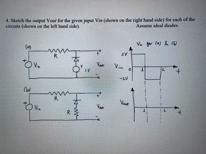
4. Sketch the output Vout for the given input Vin (shown on the right hand side) for each of the circuits (shown on the left hand side). Assume ideal diodes. Vin for (a) & (L) (a) zV R Vin Vout Vin IV -2V (b) R Vout Vin R W
4. Sketch the output Vout for the given input Vin (shown on the right hand side) for each of the circuits (shown on the left hand side). Assume ideal diodes. Vin for (a) & (L) (a) zV R Vin Vout Vin IV -2V (b) R Vout Vin R W

Chapter59: Motor Startup And Troubleshooting Basics
Section: Chapter Questions
Problem 12SQ: How is a solid-state diode tested? Explain.

Related questions

Question
Must answer for both circuits. Dont say only one will be answered.
Transcribed Image Text:4. Sketch the output Vout for the given input Vin (shown on the right hand side) for each of the
circuits (shown on the left hand side).
Assume ideal diodes.
Vin for (a) & (L)
(a)
2V
R
Vim
IV
-2V
(b)
R
Vout
Vin
Vout
R
Expert Solution
This question has been solved!
Explore an expertly crafted, step-by-step solution for a thorough understanding of key concepts.

Step by step
Solved in 2 steps with 2 images

Knowledge Booster


Learn more about
Need a deep-dive on the concept behind this application? Look no further. Learn more about this topic, electrical-engineering and related others by exploring similar questions and additional content below.Recommended textbooks for you

Electricity for Refrigeration, Heating, and Air C…
Mechanical Engineering
ISBN:
9781337399128
Author:
Russell E. Smith
Publisher:
Cengage Learning
Electricity for Refrigeration, Heating, and Air C…
Mechanical Engineering
ISBN:
9781337399128
Author:
Russell E. Smith
Publisher:
Cengage Learning