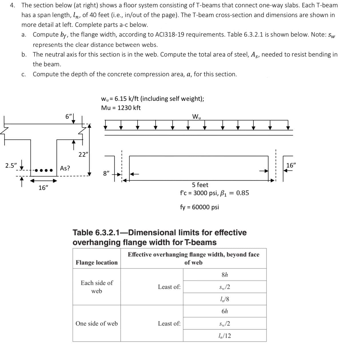
4. The section below (at right) shows a floor system consisting of T-beams that connect one-way slabs. Each T-beam has a span length, In, of 40 feet (i.e., in/out of the page). The T-beam cross-section and dimensions are shown in more detail at left. Complete parts a-c below. 2.5" a. Compute bf, the flange width, according to ACI318-19 requirements. Table 6.3.2.1 is shown below. Note: Sw represents the clear distance between webs. b. The neutral axis for this section is in the web. Compute the total area of steel, As, needed to resist bending in the beam. Compute the depth of the concrete compression area, a, for this section. C. 16" 6" As? 22" Wu 6.15 k/ft (including self weight); Mu = 1230 kft 8" Flange location Table 6.3.2.1-Dimensional limits for effective overhanging flange width for T-beams Each side of web One side of web 5 feet f'c = 3000 psi, p₁ = 0.85 fy = 60000 psi W₁ Effective overhanging flange width, beyond face of web Least of: Least of: 8h S₁/2 1₁/8 6h S₁/2 In/12 16"
4. The section below (at right) shows a floor system consisting of T-beams that connect one-way slabs. Each T-beam has a span length, In, of 40 feet (i.e., in/out of the page). The T-beam cross-section and dimensions are shown in more detail at left. Complete parts a-c below. 2.5" a. Compute bf, the flange width, according to ACI318-19 requirements. Table 6.3.2.1 is shown below. Note: Sw represents the clear distance between webs. b. The neutral axis for this section is in the web. Compute the total area of steel, As, needed to resist bending in the beam. Compute the depth of the concrete compression area, a, for this section. C. 16" 6" As? 22" Wu 6.15 k/ft (including self weight); Mu = 1230 kft 8" Flange location Table 6.3.2.1-Dimensional limits for effective overhanging flange width for T-beams Each side of web One side of web 5 feet f'c = 3000 psi, p₁ = 0.85 fy = 60000 psi W₁ Effective overhanging flange width, beyond face of web Least of: Least of: 8h S₁/2 1₁/8 6h S₁/2 In/12 16"

Chapter2: Loads On Structures
Section: Chapter Questions
Problem 1P

Related questions
Question
This is civil engineering concrete design practice. Everything needed is provided. Please answer all parts to the best of your ability. Provide thorough answer and explanation. This is only one question with a max of 3 parts due to guidelines.
Transcribed Image Text:Centroid of a composite area
y
=
Σy,Α;
ΣΑ;
First moment of area for a cross
section
Q = YA
Moment of inertia for a
rectangle, about neutral x-axis
1 = 1/2 bh³
f=
Parallel axis theorem
I = ΣĪ + Ad2
Linear stress distribution in a
cross section
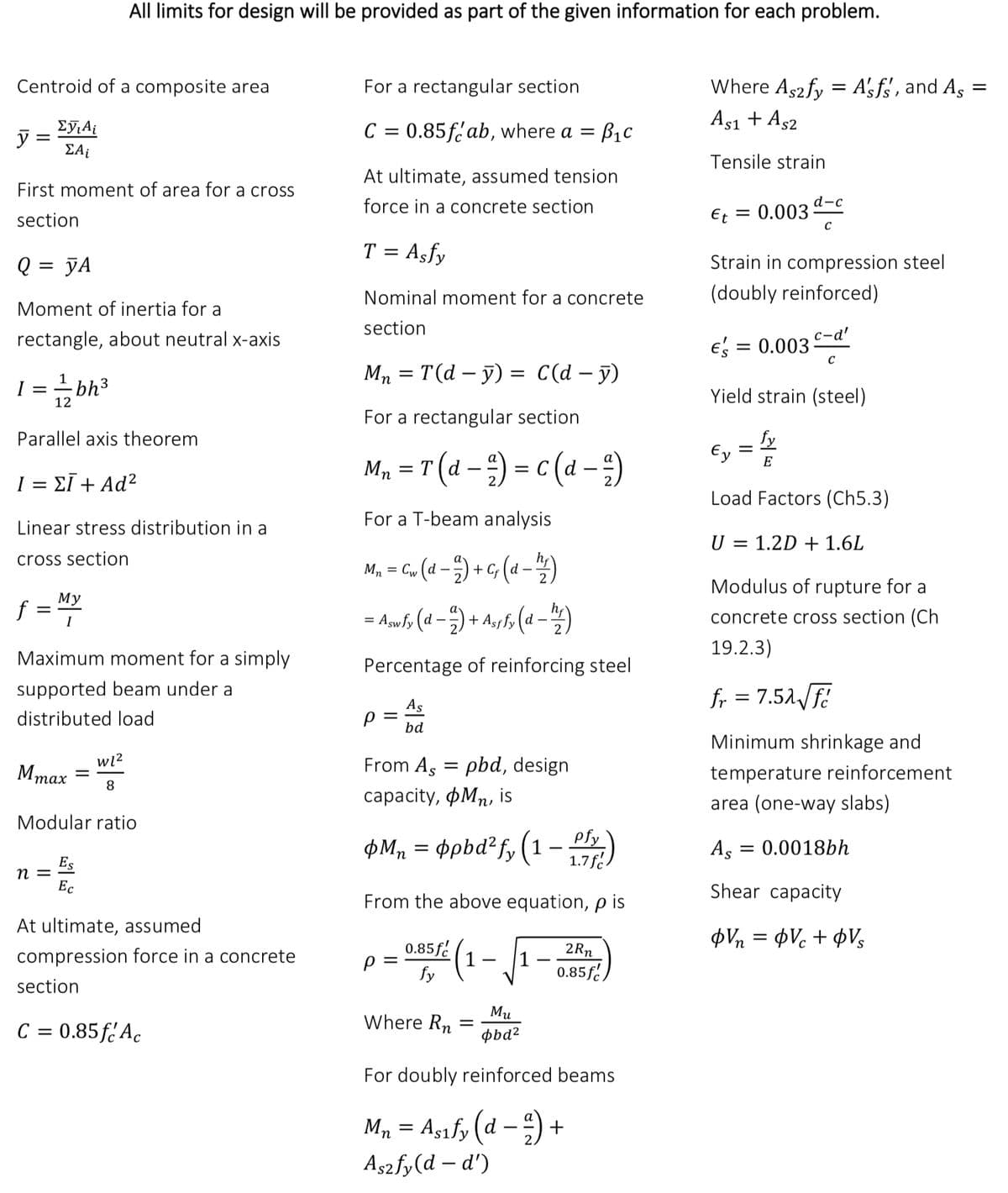
All limits for design will be provided as part of the given information for each problem.
My
I
Maximum moment for a simply
supported beam under a
distributed load
Mmax
n =
W1²
8
Modular ratio
Es
Ec
At ultimate, assumed
compression force in a concrete
section
C = 0.85fc Ac
For a rectangular section
C = 0.85f ab, where a =
At ultimate, assumed tension
force in a concrete section
T = Asfy
Nominal moment for a concrete
section
Mn = T(d - y) = C(d - y)
For a rectangular section
Mn = T (d - ²) = C (d - 2)
For a T-beam analysis
M₁ = C, (d-+G(d-)
= Asw fy (d − 2) + Assfy (d - 1/4)
Percentage of reinforcing steel
As
bd
Р
From Aspbd, design
capacity, фMn, is
þMn
pM₁ = opbd²fy (1-P)
From the above equation, p is
0.85/2 (1
fy
p =
= B1C
1-
Where Rn
1
=
Mu
obd²
For doubly reinforced beams
Mn = Asify (d-²) +
As2fy (d-d')
2Rn
0.85 f
Where Aszfy = A'sfs, and As
=
As1 + As2
Tensile strain
Et
=
0.003d-c
C
Strain in compression steel
(doubly reinforced)
c-d'
€ = 0.003-
Yield strain (steel)
=
Ey E
Load Factors (Ch5.3)
U = 1.2D + 1.6L
Modulus of rupture for a
concrete cross section (Ch
19.2.3)
fr = 7.52√ √f
Minimum shrinkage and
temperature reinforcement
area (one-way slabs)
= 0.0018bh
As =
Shear capacity
φVn = φV€ + φV
Transcribed Image Text:4. The section below (at right) shows a floor system consisting of T-beams that connect one-way slabs. Each T-beam
has a span length, In, of 40 feet (i.e., in/out of the page). The T-beam cross-section and dimensions are shown in
more detail at left. Complete parts a-c below.
2.5"
a. Compute bf, the flange width, according to ACI318-19 requirements. Table 6.3.2.1 is shown below. Note: Sw
represents the clear distance between webs.
b. The neutral axis for this section is in the web. Compute the total area of steel, As, needed to resist bending in
the beam.
Compute the depth of the concrete compression area, a, for this section.
C.
16"
6"
As?
22"
Wu = 6.15 k/ft (including self weight);
Mu 1230 kft
8"
Flange location
Table 6.3.2.1-Dimensional limits for effective
overhanging flange width for T-beams
Each side of
web
One side of web
5 feet
f'c = 3000 psi, B₁ = 0.85
fy = 60000 psi
W₁
Effective overhanging flange width, beyond face
of web
Least of:
Least of:
8h
S₁/2
1₁/8
6h
S₁/2
In/12
16"
Expert Solution
This question has been solved!
Explore an expertly crafted, step-by-step solution for a thorough understanding of key concepts.

This is a popular solution!

Trending now
This is a popular solution!

Step by step
Solved in 4 steps with 3 images

Knowledge Booster


Learn more about
Need a deep-dive on the concept behind this application? Look no further. Learn more about this topic, civil-engineering and related others by exploring similar questions and additional content below.Recommended textbooks for you

Structural Analysis (10th Edition)
Civil Engineering
ISBN:
9780134610672
Author:
Russell C. Hibbeler
Publisher:
PEARSON

Principles of Foundation Engineering (MindTap Cou…
Civil Engineering
ISBN:
9781337705028
Author:
Braja M. Das, Nagaratnam Sivakugan
Publisher:
Cengage Learning
Structural Analysis (10th Edition)
Civil Engineering
ISBN:
9780134610672
Author:
Russell C. Hibbeler
Publisher:
PEARSON
Principles of Foundation Engineering (MindTap Cou…
Civil Engineering
ISBN:
9781337705028
Author:
Braja M. Das, Nagaratnam Sivakugan
Publisher:
Cengage Learning

Fundamentals of Structural Analysis
Civil Engineering
ISBN:
9780073398006
Author:
Kenneth M. Leet Emeritus, Chia-Ming Uang, Joel Lanning
Publisher:
McGraw-Hill Education


Traffic and Highway Engineering
Civil Engineering
ISBN:
9781305156241
Author:
Garber, Nicholas J.
Publisher:
Cengage Learning