4.0 mA +10 V UCE() 6.7 V Rc VRE = 0.717 V 3.3 k2 3.0 mA B= 30 μΑ %3D Vce (1) ic 3.3 V VBE = 0.708 V 2.0 mA Vbe(1) IR = 20 µA UCE 4BE) VBE = 0.700 V 3= 15 μΑ VBE = 0.692 V 15-10 μΑ 0.708 V Q-point Upe U BE 1.0 mA 0.700 V 0.700 V VBE Load line %3D 0,692 V - OV 4 V 10 V 12 V Collector-emitter voltage (a) (b) Figure 13.1 (a) BJT biased in the active region by the voltage source VBE. A small sinusoidal signal voltage v, is applied in series with VBE and generates a similar but larger amplitude waveform at the collector; (b) load-line, Q-point, and signals for circuit of Fig. 13.1(a). is Collector curre nt
4.0 mA +10 V UCE() 6.7 V Rc VRE = 0.717 V 3.3 k2 3.0 mA B= 30 μΑ %3D Vce (1) ic 3.3 V VBE = 0.708 V 2.0 mA Vbe(1) IR = 20 µA UCE 4BE) VBE = 0.700 V 3= 15 μΑ VBE = 0.692 V 15-10 μΑ 0.708 V Q-point Upe U BE 1.0 mA 0.700 V 0.700 V VBE Load line %3D 0,692 V - OV 4 V 10 V 12 V Collector-emitter voltage (a) (b) Figure 13.1 (a) BJT biased in the active region by the voltage source VBE. A small sinusoidal signal voltage v, is applied in series with VBE and generates a similar but larger amplitude waveform at the collector; (b) load-line, Q-point, and signals for circuit of Fig. 13.1(a). is Collector curre nt

Delmar's Standard Textbook Of Electricity
7th Edition
ISBN:9781337900348
Author:Stephen L. Herman
Publisher:Stephen L. Herman
Chapter19: Capacitors
Section: Chapter Questions
Problem 3RQ: A capacitor uses air as a dielectric and has a capacitance of 3 F. A dielectric material is inserted...

Related questions

Question
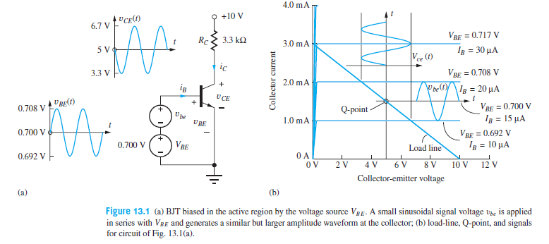
(a) Suppose υbe(t) = 0.005 sin 2000πt V in the bipolar amplifier as shown . Write expressions for υbe(t), vce(t), and υCE(t). (b) What is the maximum value of IC that corresponds to the active region of operation?
Transcribed Image Text:4.0 mA
+10 V
UCE()
6.7 V
Rc
VRE = 0.717 V
3.3 k2
3.0 mA
B= 30 μΑ
%3D
Vce (1)
ic
3.3 V
VBE = 0.708 V
2.0 mA
Vbe(1)
IR = 20 µA
UCE
4BE)
VBE = 0.700 V
3= 15 μΑ
VBE = 0.692 V
15-10 μΑ
0.708 V
Q-point
Upe
U BE
1.0 mA
0.700 V
0.700 V
VBE
Load line
%3D
0,692 V -
OV
4 V
10 V
12 V
Collector-emitter voltage
(a)
(b)
Figure 13.1 (a) BJT biased in the active region by the voltage source VBE. A small sinusoidal signal voltage v, is applied
in series with VBE and generates a similar but larger amplitude waveform at the collector; (b) load-line, Q-point, and signals
for circuit of Fig. 13.1(a).
is
Collector curre nt
Expert Solution
This question has been solved!
Explore an expertly crafted, step-by-step solution for a thorough understanding of key concepts.

This is a popular solution!

Trending now
This is a popular solution!

Step by step
Solved in 3 steps with 5 images

Knowledge Booster


Learn more about
Need a deep-dive on the concept behind this application? Look no further. Learn more about this topic, electrical-engineering and related others by exploring similar questions and additional content below.Recommended textbooks for you
Delmar's Standard Textbook Of Electricity
Electrical Engineering
ISBN:
9781337900348
Author:
Stephen L. Herman
Publisher:
Cengage Learning

Electricity for Refrigeration, Heating, and Air C…
Mechanical Engineering
ISBN:
9781337399128
Author:
Russell E. Smith
Publisher:
Cengage Learning
Delmar's Standard Textbook Of Electricity
Electrical Engineering
ISBN:
9781337900348
Author:
Stephen L. Herman
Publisher:
Cengage Learning
Electricity for Refrigeration, Heating, and Air C…
Mechanical Engineering
ISBN:
9781337399128
Author:
Russell E. Smith
Publisher:
Cengage Learning