4.5 nA CHAPTER 7 CAPACITORS AND INDUCTORS 15. For each circuit shown in Fig. 7.46, calculate the voltage labeled vc. "C + 13 Ω 13 S2 1343 10 (2 ww 792 (a) ww 3 mF 50 www 4.5 nA 10 2 www + 3 mFc 792 (b) www 592 www
4.5 nA CHAPTER 7 CAPACITORS AND INDUCTORS 15. For each circuit shown in Fig. 7.46, calculate the voltage labeled vc. "C + 13 Ω 13 S2 1343 10 (2 ww 792 (a) ww 3 mF 50 www 4.5 nA 10 2 www + 3 mFc 792 (b) www 592 www

Introductory Circuit Analysis (13th Edition)
13th Edition
ISBN:9780133923605
Author:Robert L. Boylestad
Publisher:Robert L. Boylestad
Chapter1: Introduction
Section: Chapter Questions
Problem 1P: Visit your local library (at school or home) and describe the extent to which it provides literature...

Related questions
Question
100%
Can you complete question 15 for me, please? I know how to complete this question when I have a voltage power source, but not with an amperage power source.
Transcribed Image Text:4.5 NA
DP
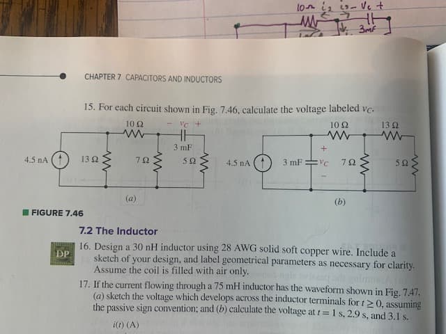
CHAPTER 7 CAPACITORS AND INDUCTORS
FIGURE 7.46
15. For each circuit shown in Fig. 7.46, calculate the voltage labeled vc.
VC +
13 Ω
10 Ω
www
13 92
ww
1092
www
792
(a)
www
3 mF
592
www
10th 1₂ 23- Ve +
ww
JV. 3m²
4.5 nA
+
3 mFvc 792
(b)
www
592
ww
7.2 The Inductor
16. Design a 30 nH inductor using 28 AWG solid soft copper wire. Include a
sketch of your design, and label geometrical parameters as necessary for clarity.
Assume the coil is filled with air only.
17. If the current flowing through a 75 mH inductor has the waveform shown in Fig. 7.47,
(a) sketch the voltage which develops across the inductor terminals for t≥0, assuming
the passive sign convention; and (b) calculate the voltage at t= 1 s, 2.9 s, and 3.1 s.
i(t) (A)
Expert Solution
This question has been solved!
Explore an expertly crafted, step-by-step solution for a thorough understanding of key concepts.

This is a popular solution!

Trending now
This is a popular solution!

Step by step
Solved in 3 steps with 4 images

Knowledge Booster


Learn more about
Need a deep-dive on the concept behind this application? Look no further. Learn more about this topic, electrical-engineering and related others by exploring similar questions and additional content below.Recommended textbooks for you
Introductory Circuit Analysis (13th Edition)
Electrical Engineering
ISBN:
9780133923605
Author:
Robert L. Boylestad
Publisher:
PEARSON

Delmar's Standard Textbook Of Electricity
Electrical Engineering
ISBN:
9781337900348
Author:
Stephen L. Herman
Publisher:
Cengage Learning

Programmable Logic Controllers
Electrical Engineering
ISBN:
9780073373843
Author:
Frank D. Petruzella
Publisher:
McGraw-Hill Education
Introductory Circuit Analysis (13th Edition)
Electrical Engineering
ISBN:
9780133923605
Author:
Robert L. Boylestad
Publisher:
PEARSON
Delmar's Standard Textbook Of Electricity
Electrical Engineering
ISBN:
9781337900348
Author:
Stephen L. Herman
Publisher:
Cengage Learning
Programmable Logic Controllers
Electrical Engineering
ISBN:
9780073373843
Author:
Frank D. Petruzella
Publisher:
McGraw-Hill Education

Fundamentals of Electric Circuits
Electrical Engineering
ISBN:
9780078028229
Author:
Charles K Alexander, Matthew Sadiku
Publisher:
McGraw-Hill Education

Electric Circuits. (11th Edition)
Electrical Engineering
ISBN:
9780134746968
Author:
James W. Nilsson, Susan Riedel
Publisher:
PEARSON

Engineering Electromagnetics
Electrical Engineering
ISBN:
9780078028151
Author:
Hayt, William H. (william Hart), Jr, BUCK, John A.
Publisher:
Mcgraw-hill Education,