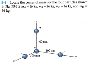
5-4 Locate the center of mass for the four particles shown. in Fig, P54 if m= 16 kg, mg = 24 kg, mc = 14 kg, and mp = 36 kg. 400 mm B 500 mm 300 mm


Q: Consider the Bar/Rollers/Wire system of the figure. The Bar and Rollers assembly weighs 60 lbs, with…
A: Given data weight of bar and rollers assembly (w) = 60 lbs To determine 1) draw a free body…
Q: P4-1. Draw the free-body diagram of object. 600 N m -2 m- 3m
A: Given data Applied moment = 600Nm To draw the free body diagram of the object with given moment
Q: Three uniform disks made up of two same materials with one being lighter compared to the other…
A: given; Three uniform disks made up of two same materials with one being lighter compared to the…
Q: A lunch tray is being held in one hand, as the figure illustrates. The mass of the tray itself is…
A:
Q: 1. The man is holding up the 35-kg ladder ABC by pushing perpendicular to the ladder. If the maximum…
A:
Q: 2. If the mass of cylinder C is 40 kg, determine the mass of cylinder A in order to hold the…
A: The mass of the cylinder C is mC=40 kg. Standard Values- The acceleration due to gravity is g=9.81…
Q: Part A The pendulum in (Figure 1) consists of a 2-kg disk and slender rods AB and DC which have a…
A:
Q: (Q3] (a) The wooden rod AB supports the roof ADC. If the mass of roof is 70 Kg and its weight acting…
A:
Q: The tractor shovel shown (Figure 4) carries a 520 kg load that has its center of mass at H. The…
A: Find the reaction at point E.
Q: In reference to the figure below, if u,-0.2 supplied to all four wheels of the 1.5 Mg vehicle with…
A:
Q: The spring has a stiffness k-24 N/m and the bar AB has a mass of 2.8 kg. What is the change in the…
A:
Q: The 84 kg gate has a center of mass located at G. If A supports only a horizontal force and B can þe…
A: ΣFy = 0 By - 84(9.81) = 0 By=824 N ΣMB = 0 Ax (1) - (9.81)(1.25) = 0 Ax= 1030 N
Q: 1. Determine the second mass moments I, , 3d - 3d I, and J, for the plate shown. The plate has…
A:
Q: II. Draw the free-body diagram of parts A, B, C, D and E of the following structure:
A:
Q: 5-10 Three bodies with masses of 3, 6, and 7 kg are lo- cated at points (4, -3, 1), (-1, 3, 2), and…
A: The center of mass of an object is the point at which the total mass of the object can be assumed to…
Q: P4-2. Draw the free-body diagram of object. 300 N Im. 5m.
A: Free Body Diagram. Plotting of a Free body diagram is used to simplify the given problem statement.…
Q: *5-60. The platform scale consists of a combination of third and first class levers so that the load…
A: Consider the free body diagram of the arm AB as shown below. Taking the moment about the point A,
Q: P4-2. Draw the free-body diagram of object. 400 N - 2 m- -2 m-
A: Free Body Diagram (FBD) is the graphical illustration of the member of the system showing all the…
Q: Figure 1 shows a simple system to lift a heavy load. The dimensions a = 3.6 m and b = 1.2 m. The…
A: given : W = 20000 g = 20kg CW = 45000 g = 45 kg
Q: Problem 5.2
A: A free-body diagram is a method to analyze the external forces and reactions acting on a given body…
Q: 5-61. The platform scale consists of a combination of third and first class levers so that the load…
A: Draw FBD for the member CD as shown below, Consider the equilibrium of member about C, And apply…
Q: P4-1. Draw the free-body diagram of object. 400 N/m -3 m -3m-
A: Given, UVL intensity = 400 N/m Converting UVL into Point Load = =12×Load×Length= 12×400×6=1200 N/m…
Q: Draw the free-body diagram for the following problem. The rod shown.
A: Let, HA be the horizontal support reaction at point A, and RA be the vertical support reaction at A.…
Q: 5-107 Determine the resultant R of the system of dis- tributed loads on the beam of Fig. P5-107 and…
A: Consider the Section 1 from support A till the 4 ft length (where the parabolic loading ends). The…
Q: he block has a mass of 5.8 kg and rests on the smooth plane. Determine the unstretched length of the…
A: Given:m=5.8 KgK=200 N/m
Q: 5-9* Three bodies with masses of 2, 4, and 6 slugs are lo- cated at points (2, 3, 4), (3, -4, 5),…
A: Given Data: The mass of body 1 is m1 = 2 slug. The mass of body 2 is m2 = 4 slug. The mass of body…
Q: 3-5.21. Find the distance x (measured along AB) at which a horizontal force of 60 lb should be…
A:
Q: 5-3 Locate the center of gravity for the four particles shown in Fig.- P5-3 if WA = 20 lb, Wp = 25…
A: Given Data: The weight of particle A is WA = 20 lb. The weight of particle B is WB = 25 lb. The…
Q: A force Plt) acting on the Pistor Causes Crankshaft AB to rotate . The mass per each Bar ús T, uunit…
A: Solution: Given Data: mb=σmp=σL
Q: P4-1. Draw the free-body diagram of object. 200 N/m в -2 m
A: Solution :As we can see in the diagram , that A is fixed support and B is a roller support .So…
Q: At the instant shown in Figure 5, the block A is descending at 1.5 m/s. The cylinder B is rotating…
A:
Q: Q3/ A shaft has three eccentric of mass 1 kg cach. The central plane of the eccentrics is 50 mm…
A:
Q: 3-27. If cylinder E weighs 30 lb and 0 = 15°, determine the weight of cylinder F. 30 45° F
A:
Q: P4-1. Draw the free-body diagram of object. 500 N в
A: In the given figure an object of the length 5 m is fixed at end A and attached with string at point…
Q: The disc given below has 0.06 kg of unbalanced mass on the Y-axis and 0.03 kg of unbalanced space on…
A:
Q: 2) If the mass of cylinder C is 40 kg, determine the mass of cylinder A in order to hold the…
A:
Q: The hand truck and its contents have a mass of 58 kg with center of gravity at G. (Eigure 1) Part A…
A:
Q: P4-1. Draw the free-body diagram of object. 30 400 N в. - 2 m 1m
A: In the given figure a beam shown which is fixed at point C and free at the point A. It is supported…
Q: Determine the force P required to maintain the M-kg engine in the position shown in the figure. The…
A:
Q: 3-19. Determine the unstretched length of DB to hold the 40-kg crate in the position shown. Take k =…
A:
Q: QUESTION 1 A rotating shafR is supported by two bearings. The shaft is uobalanced due to a 4.5 kg…
A:
Q: P4-2. Draw the free-body diagram of object. 3m 500 N
A: In this diagram, there are three fixed supports at points A, B and C. In case of Three dimensional…
Q: P4-1. Draw the free-body diagram of object. 500 N 4 m- 30
A: Drawing the fee body diagram of the point A
Q: Q4/. If the mass of cylinder A is 50 kg, determine the mass of cylinder C in order to hold the…
A:
Q: 6-49 Determine the force P required to push the 300-lb cylinder over the small block shown in Fig. P…
A: Given data: Weight of the cylinder = 300 lb The arrangement as shown in the…
Q: A motor supplies a constant torque M = 6 kNm to the winding drum that operates the elevator. The…
A:
Q: A window cleaner is pulling himself up to a pulley that consists of two disks welded together as…
A:
Q: The grinder has a force of 400 N in the direction shown at the bottom. The grinder has a mass of 300…
A: Given: Let us consider the given image, Force, F=400 N Mass, m=300 kg To find: The force of…
Q: 3-19. Determine the unstretched length of DB to hold the 40-kg crate in the position shown. Take k…
A:

Step by step
Solved in 2 steps with 3 images

- 5 answer A and B including free body diagramThe figure shows a mechanical model of the Russel fracture traction device and the leg. The leg is held in balance in the position indicated by the two weights attached to the two cables. The total weight of the leg and the cast is W=200 N. The horizontal distance between points A and B where the cables are attached to the leg is L=100 cm and the vertical distance is d=10 cm . Point C is the center of gravity of the cast and leg at three quarters of the L measured from point A ( 3L/4= 75 cm) . The angle that cable 2 makes with the horizontal is measured as β=40 ° . Accordingly, in order for the leg to remain in balance in the position shown; a) Find the tensile force T 1 in cable 1 . (Write your result in N ) b) Find the tensile force T 2 in cable 2 . (Write your result in N ) c) Find the angle α of cable 1 with the horizontalA window cleaner is pulling himself up to a pulley that consists of two disks welded together as shown. The person is currently pulling straight down on the rope in his hands with a force of magnitude 580.4 N. The other rope is also vertical and is attached to the person's center of mass. The person's mass is 74.2 kg, the pulley's total moment of inertia is 395 kgm2, the radius of the small disk is 0.39 m, and the radius of the big disk is 0.73 m.What is the magnitude of the acceleration of the person's center of mass?
- A “swing ride” is shown in the figure. For b=2.2 m , L=5 m and θ=41o ,neglect the mass of the cables and treat the chair and person as one particle with mass m=25 kg: 1-Radius of horizontal circle (m) a. 9.8645312609146 - b. 5.4802951449525 - c. 7.6724132029335 - d. 8.7684722319241 - e. 4.384236115962 2-Tension in cables (N) 3-Velocity of the child (m/s) 4- Maximum speed if the maximum tension in the cables is 1470 NThe disc given below has 0.06 kg of unbalanced mass on the Y-axis and 0.03 kg of unbalanced space on the X-axis at the same radius. Determine the required mass and position on the same radius to balance this disk in the plane. (mass can be added or subtracted.)The figure below is a system consisting of two masses MA = 1.82 kg and MB = 3.6 kg, whose distance from the pore axis is R₁ = R₂ = 15 cm, while the angular positions are 0₁ = 30° and 0 = 150° . Determine the weight and position of the balancing mass placed on planes C and D if the distance from the axis RC = RD = 15 cm.
- The figure shows the Russel fracture traction device and a mechanical model of the leg. The leg is held in balance in the position indicated by the two weights attached to the two cables. The total weight of the leg and the cast is W=250 N. The distance between the points A and B where the cables are attached to the leg is given as L=100 cm and the angle of the leg with the horizontal is γ=6°. Point C is the center of gravity of the cast and leg at three quarters of the L measured from point A (3L/4= 75 cm). The angle that cable 2 makes with the horizontal is measured as β=40°. Accordingly, in order for the leg to remain in balance in the shown position; a) Find the tensile force T1 in cable 1. (Write your result in N) Answerb) Find the tensile force T2 in cable 2. (Write your result in N) Answerc) Find the angle α of cable 1 with the horizontal. ResponseThe figure shows the Russel fracture traction device and a mechanical model of the leg. The leg is held in balance in the position indicated by the two weights attached to the two cables. The combined weight of the leg and cast is W=180 N. The distance between the points A and B where the cables are attached to the leg is given as L=100 cm and the angle of the leg with the horizontal is given as γ=8°. Point C is the center of gravity of the cast and leg at three quarters of the L measured from point A (3L/4= 75 cm). The angle that cable 2 makes with the horizontal is measured as β=50°. Accordingly, in order for the leg to remain in balance in the shown position; a) Find the tensile force T1 in cable 1. (Write your result in N)b) Find the tensile force T2 in cable 2. (Write your result in N)c) Find the angle α of cable 1 with the horizontal.The figure shows the Russel fracture traction device and a mechanical model of the leg. The leg is held in balance in the position indicated by the two weights attached to the two cables. The combined weight of the leg and the cast is W=210 N. The horizontal distance between points A and B where the cables are attached to the leg is L=100 cm and the vertical distance is d=6 cm. Point C is the center of gravity of the cast and leg at three quarters of the L measured from point A (3L/4= 75 cm). The angle that cable 2 makes with the horizontal is measured as β=33°. Accordingly, in order for the leg to remain in balance in the shown position; a) Find the tensile force T1 in cable 1. (Write your result in N) b) Find the tensile force T2 in cable 2. (Write your result in N) c) Find the angle α of cable 1 with the horizontal.