(5) Figure below shows the RL circuit. (a) Calculate the Apparent Power S, Reactive Power Q True Power P and power factor. (b) Sketch the Power Triangle – include S, P, Q and 0. Write the magnitudes and units. (c) If one capacitor of 1 uF is connected parallel to the R-L components, find the new Reactive Power Q, Apparent Power S and new phase angle 0. ell 200 Q sine 50 Hz V= 240 V 1.086 A
(5) Figure below shows the RL circuit. (a) Calculate the Apparent Power S, Reactive Power Q True Power P and power factor. (b) Sketch the Power Triangle – include S, P, Q and 0. Write the magnitudes and units. (c) If one capacitor of 1 uF is connected parallel to the R-L components, find the new Reactive Power Q, Apparent Power S and new phase angle 0. ell 200 Q sine 50 Hz V= 240 V 1.086 A

Delmar's Standard Textbook Of Electricity
7th Edition
ISBN:9781337900348
Author:Stephen L. Herman
Publisher:Stephen L. Herman
Chapter17: Resistive-inductive Series Circuits
Section: Chapter Questions
Problem 2PP: Assume that the voltage drop across the resistor, ER, is 78 V, that the voltage drop across the...

Related questions
Question
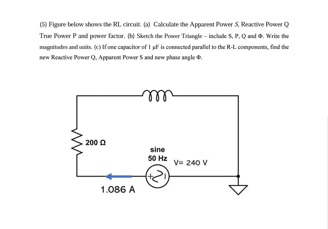
Transcribed Image Text:(5) Figure below shows the RL circuit. (a) Calculate the Apparent Power S, Reactive Power Q
True Power P and power factor. (b) Sketch the Power Triangle – include S, P, Q and 0. Write the
magnitudes and units. (c) If one capacitor of 1 µF is connected parallel to the R-L components, find the
new Reactive Power Q, Apparent Power S and new phase angle 0.
ll
200 Q
sine
50 Hz
V= 240 V
1.086 A
Expert Solution
This question has been solved!
Explore an expertly crafted, step-by-step solution for a thorough understanding of key concepts.

This is a popular solution!

Trending now
This is a popular solution!

Step by step
Solved in 3 steps with 9 images

Knowledge Booster


Learn more about
Need a deep-dive on the concept behind this application? Look no further. Learn more about this topic, electrical-engineering and related others by exploring similar questions and additional content below.Recommended textbooks for you
Delmar's Standard Textbook Of Electricity
Electrical Engineering
ISBN:
9781337900348
Author:
Stephen L. Herman
Publisher:
Cengage Learning
Delmar's Standard Textbook Of Electricity
Electrical Engineering
ISBN:
9781337900348
Author:
Stephen L. Herman
Publisher:
Cengage Learning