5 V 390 47052 Action Figure 1 Bridge circuit 3.31 R₁-33052 ww Love 1.2kQ
5 V 390 47052 Action Figure 1 Bridge circuit 3.31 R₁-33052 ww Love 1.2kQ

Introductory Circuit Analysis (13th Edition)
13th Edition
ISBN:9780133923605
Author:Robert L. Boylestad
Publisher:Robert L. Boylestad
Chapter1: Introduction
Section: Chapter Questions
Problem 1P: Visit your local library (at school or home) and describe the extent to which it provides literature...

Related questions
Question
Submission of result report for thevenin equivalent circuit.
You have to take help from no.4 i.e experiment content and analysis and value are given below and also writeconclusions
Value
4.1 Voltage= 0.326 v
4.2 Vth= 1.405 v
Rth= 1.081 Kohm
4.3 Rth= 1.081 Kohm
RL= 0.326v
Transcribed Image Text:4. Experimental contents and analysis
If there are no other instructions, record the measurement up to three significant digits.
*Connect the power lines of the DMM and the DC Power Supply to the 220 v power outlet and press the power button
according to the instructions of the assistant before starting the experiment. Since all electrical and electronic equipment
consists of parts whose characteristics change with temperature, accurate measurement should be performed after
waiting for about 10 minutes after turning on the power. The power line must be connected to a 220 V power outlet |
with a ground terminal. Otherwise, it is often impossible to measure!
*Caution: Never change the voltage, current resistance measurement mode when the DMM is connected to the circuit! That is,
change the measurement mode of the DMM before connecting to the circuit or element!
* CAUTION: Always connect black lines to low voltage, or ground, and then connect black lines to
each other first, then red lines!
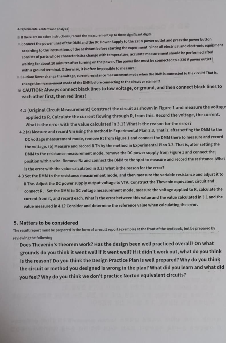
4.1 (Original Circuit Measurement) Construct the circuit as shown in Figure 1 and measure the voltage
applied to R. Calculate the current flowing through R, from this. Record the voltage, the current.
What is the error with the value calculated in 3.1? What is the reason for the error?
4.2 (a) Measure and record Vm using the method in Experimental Plan 3.3. That is, after setting the DMM to the
DC voltage measurement mode, remove Rt from Figure 1 and connect the DMM there to measure and record
the voltage. (b) Measure and record R Th by the method in Experimental Plan 3.3. That is, after setting the
DMM to the resistance measurement mode, remove the DC power supply from Figure 1 and connect the
position with a wire. Remove Rz and connect the DMM to the spot to measure and record the resistance. What
is the error with the value calculated in 3.2? What is the reason for the error?
4.3 Set the DMM to the resistance measurement mode, and then measure the variable resistance and adjust it to
R The. Adjust the DC power supply output voltage to VTA. Construct the Thevenin equivalent circuit and
connect R,. Set the DMM to DC voltage measurement mode, measure the voltage applied to R, calculate the
current from it, and record each. What is the error between this value and the value calculated in 3.1 and the
value measured in 4.1? Consider and determine the reference value when calculating the error.
5. Matters to be considered
The result report must be prepared in the form of a result report (example) at the front of the textbook, but be prepared by
reviewing the following
Does Thevenin's theorem work? Has the design been well practiced overall? On what
grounds do you think it went well if it went well? If it didn't work out, what do you think
is the reason? Do you think the Design Practice Plan is well prepared? Why do you think
the circuit or method you designed is wrong in the plan? What did you learn and what did
you feel? Why do you think we don't practice Norton equivalent circuits?
Transcribed Image Text:Design Practice 4. Design of Thevenin Equivalent Circuit
1. Purpose: Design, manufacture, and measure Thevenin equivalent circuit and compare it with the original circuit and the theoretical value.
2. Preparations
* Basic Equipment and Lines
Function generator: 1 unit
DC Power Supply (Regulated DC Power supply (Max 20 v or higher): 1 unit
Digital Oscillo oscilloscopes with 2 Probe: 1
Digital Multimeter (hereinafter DMM, using 220V alternating current): 1 unit
40 cm connection wire: 4 red lines, 4 black lines (one side can be plugged
into the instrument, the other tongs)
Breadboard: 1
Jumper Wire Kit: 1 piece
Parts
Lead resistance: 1/4 w, 5% 1 each
330 Ω, 390 Ω, 470 Ω, 1 ΚΩ, 1,2 ΚΩ, 3.3 ΚΩ
Variable resistance: 2 20kn.2W classes
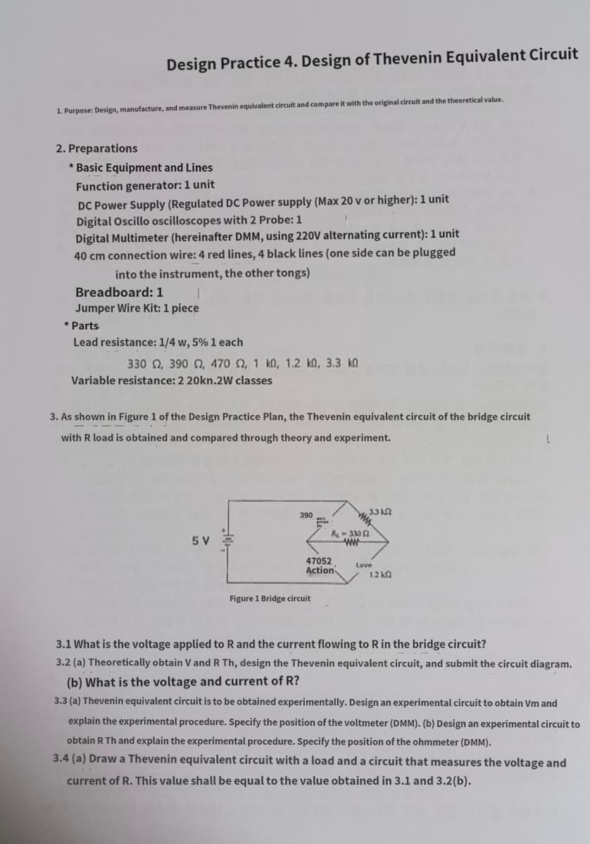
3. As shown in Figure 1 of the Design Practice Plan, the Thevenin equivalent circuit of the bridge circuit
with R load is obtained and compared through theory and experiment.
5 V
390
47052
Action
Figure 1 Bridge circuit
3.3 k
R₁-33052
ww
Love
1.2 k
3.1 What is the voltage applied to R and the current flowing to R in the bridge circuit?
3.2 (a) Theoretically obtain V and R Th, design the Thevenin equivalent circuit, and submit the circuit diagram.
(b) What is the voltage and current of R?
3.3 (a) Thevenin equivalent circuit is to be obtained experimentally. Design an experimental circuit to obtain Vm and
explain the experimental procedure. Specify the position of the voltmeter (DMM). (b) Design an experimental circuit to
obtain R Th and explain the experimental procedure. Specify the position of the ohmmeter (DMM).
3.4 (a) Draw a Thevenin equivalent circuit with a load and a circuit that measures the voltage and
current of R. This value shall be equal to the value obtained in 3.1 and 3.2(b).
Expert Solution
This question has been solved!
Explore an expertly crafted, step-by-step solution for a thorough understanding of key concepts.

Step by step
Solved in 5 steps with 5 images

Knowledge Booster


Learn more about
Need a deep-dive on the concept behind this application? Look no further. Learn more about this topic, electrical-engineering and related others by exploring similar questions and additional content below.Recommended textbooks for you
Introductory Circuit Analysis (13th Edition)
Electrical Engineering
ISBN:
9780133923605
Author:
Robert L. Boylestad
Publisher:
PEARSON

Delmar's Standard Textbook Of Electricity
Electrical Engineering
ISBN:
9781337900348
Author:
Stephen L. Herman
Publisher:
Cengage Learning

Programmable Logic Controllers
Electrical Engineering
ISBN:
9780073373843
Author:
Frank D. Petruzella
Publisher:
McGraw-Hill Education
Introductory Circuit Analysis (13th Edition)
Electrical Engineering
ISBN:
9780133923605
Author:
Robert L. Boylestad
Publisher:
PEARSON
Delmar's Standard Textbook Of Electricity
Electrical Engineering
ISBN:
9781337900348
Author:
Stephen L. Herman
Publisher:
Cengage Learning
Programmable Logic Controllers
Electrical Engineering
ISBN:
9780073373843
Author:
Frank D. Petruzella
Publisher:
McGraw-Hill Education

Fundamentals of Electric Circuits
Electrical Engineering
ISBN:
9780078028229
Author:
Charles K Alexander, Matthew Sadiku
Publisher:
McGraw-Hill Education

Electric Circuits. (11th Edition)
Electrical Engineering
ISBN:
9780134746968
Author:
James W. Nilsson, Susan Riedel
Publisher:
PEARSON

Engineering Electromagnetics
Electrical Engineering
ISBN:
9780078028151
Author:
Hayt, William H. (william Hart), Jr, BUCK, John A.
Publisher:
Mcgraw-hill Education,