5. Given v = 200 sin 377t V and i = 8 sin (377t-30°) A for an ac circuit. Determine (a) the power factor, (b) true power, (c) apparent power, and (d) reactive power.
5. Given v = 200 sin 377t V and i = 8 sin (377t-30°) A for an ac circuit. Determine (a) the power factor, (b) true power, (c) apparent power, and (d) reactive power.

Power System Analysis and Design (MindTap Course List)
6th Edition
ISBN:9781305632134
Author:J. Duncan Glover, Thomas Overbye, Mulukutla S. Sarma
Publisher:J. Duncan Glover, Thomas Overbye, Mulukutla S. Sarma
Chapter2: Fundamentals
Section: Chapter Questions
Problem 2.10P: For the circuit element of Problem 2.3, calculate (a) the instantaneous power absorbed, (b) the real...

Related questions
Question
A. Answer 5
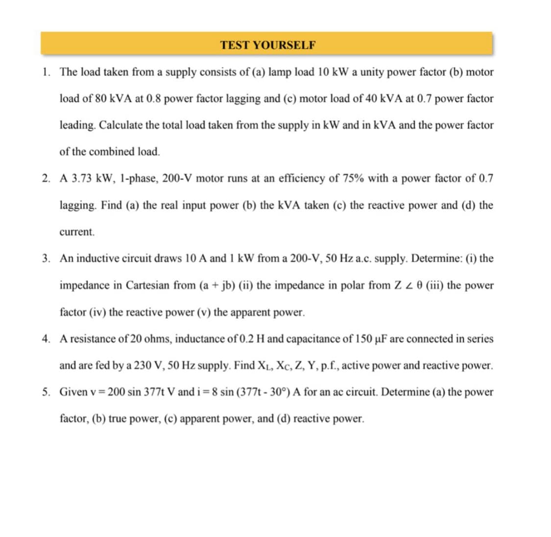
Transcribed Image Text:TEST YOURSELF
1. The load taken from a supply consists of (a) lamp load 10 kW a unity power factor (b) motor
load of 80 kVA at 0.8 power factor lagging and (c) motor load of 40 kVA at 0.7 power factor
leading. Calculate the total load taken from the supply in kW and in kVA and the power factor
of the combined load.
2. A 3.73 kW, 1-phase, 200-V motor runs at an efficiency of 75% with a power factor of 0.7
lagging. Find (a) the real input power (b) the kVA taken (c) the reactive power and (d) the
current.
3. An inductive circuit draws 10 A and 1 kW from a 200-V, 50 Hz a.c. supply. Determine: (i) the
impedance in Cartesian from (a + jb) (ii) the impedance in polar from Z Z 0 (iii) the power
factor (iv) the reactive power (v) the apparent power.
4. A resistance of 20 ohms, inductance of 0.2 H and capacitance of 150 µF are connected in series
and are fed by a 230 V, 50 Hz supply. Find X₁, Xc, Z, Y, p.f., active power and reactive power.
5. Given v = 200 sin 377t V and i = 8 sin (377t-30°) A for an ac circuit. Determine (a) the power
factor, (b) true power, (c) apparent power, and (d) reactive power.
Expert Solution
This question has been solved!
Explore an expertly crafted, step-by-step solution for a thorough understanding of key concepts.

This is a popular solution!

Trending now
This is a popular solution!

Step by step
Solved in 2 steps with 2 images

Knowledge Booster


Learn more about
Need a deep-dive on the concept behind this application? Look no further. Learn more about this topic, electrical-engineering and related others by exploring similar questions and additional content below.Recommended textbooks for you
Power System Analysis and Design (MindTap Course …
Electrical Engineering
ISBN:
9781305632134
Author:
J. Duncan Glover, Thomas Overbye, Mulukutla S. Sarma
Publisher:
Cengage Learning
Power System Analysis and Design (MindTap Course …
Electrical Engineering
ISBN:
9781305632134
Author:
J. Duncan Glover, Thomas Overbye, Mulukutla S. Sarma
Publisher:
Cengage Learning