5.5-5.15 For the rigid frames shown in Figures P5-5 through P5-15, determine the displace- ments and rotations of the nodes, the element forces, and the reactions. The values of E, A, and I to be used are listed next to each figure.
5.5-5.15 For the rigid frames shown in Figures P5-5 through P5-15, determine the displace- ments and rotations of the nodes, the element forces, and the reactions. The values of E, A, and I to be used are listed next to each figure.

Mechanics of Materials (MindTap Course List)
9th Edition
ISBN:9781337093347
Author:Barry J. Goodno, James M. Gere
Publisher:Barry J. Goodno, James M. Gere
Chapter11: Columns
Section: Chapter Questions
Problem 11.2.11P: The figure shows an idealized structure consisting of an L-shaped rigid bar structure supported by...

Related questions

Question
Do not give answer in image formet and hand writing
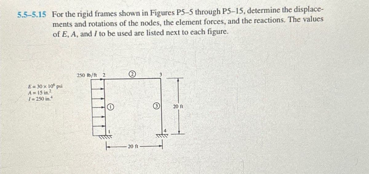
Transcribed Image Text:5.5-5.15 For the rigid frames shown in Figures P5-5 through P5-15, determine the displace-
ments and rotations of the nodes, the element forces, and the reactions. The values
of E, A, and I to be used are listed next to each figure.
E=30 × 10° psi
A= 15 in.2
1=250 in.4
250 lb/ft 2
20 ft
20 ft
Expert Solution
This question has been solved!
Explore an expertly crafted, step-by-step solution for a thorough understanding of key concepts.

This is a popular solution!

Trending now
This is a popular solution!

Step by step
Solved in 4 steps with 3 images

Knowledge Booster


Learn more about
Need a deep-dive on the concept behind this application? Look no further. Learn more about this topic, mechanical-engineering and related others by exploring similar questions and additional content below.Recommended textbooks for you
Mechanics of Materials (MindTap Course List)
Mechanical Engineering
ISBN:
9781337093347
Author:
Barry J. Goodno, James M. Gere
Publisher:
Cengage Learning
Mechanics of Materials (MindTap Course List)
Mechanical Engineering
ISBN:
9781337093347
Author:
Barry J. Goodno, James M. Gere
Publisher:
Cengage Learning