
Mechanics of Materials (MindTap Course List)
9th Edition
ISBN: 9781337093347
Author: Barry J. Goodno, James M. Gere
Publisher: Cengage Learning
expand_more
expand_more
format_list_bulleted
Videos
Textbook Question
Chapter 5, Problem 5.12.11P
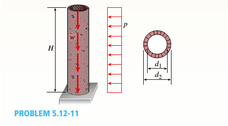
A cylindrical brick chimney of height H weighs w = 825 lb/ft of height (see figure). The inner and outer diameters are d1= 3 ft and d2= 4 ft, respectively. The wind pressure against the side of the chimney is p = 10 lb/ft2 of projected area.
Determine the maximum height H if there is to be no tension in the brickwork.
Expert Solution & Answer

Trending nowThis is a popular solution!

Students have asked these similar questions
A 20.0-m-long uniform beam weighing 560 N rests on walls A and B, as shown in the figure (Figure 1).
a) Find the maximum weight of a person who can walk to the extreme end D without tipping the beam.
b) Find the forces that the walls A and B exert on the beam when the person is standing at D
c) Find the forces that the walls A and B exert on the beam when the person is standing at a point 2.8 m to the right of B.
d) Find the forces that the walls A and B exert on the beam when the person is standing 1.5 m to the right of A.
The plate shown in Figure is supported by a roller and a cable in the x-direction at A, a ball-and-socket joint at B, and a roller at C. A force F = 8.1 kN is applied at the centroid of the plate parallel to the yz-plane and making an angle of θ = 40 ∘ with the xy-plane. The sides AB and BC of the plate have length L = 1.5 m .
1) What is the reaction force in the y-direction at point B? Let a positive force act in the positive y-direction?
2) What is the reaction force in the z-direction at point C?
3) What is the reaction force in the z-direction at point A?
The plate shown in (Figure is supported by a roller and a cable in the x-direction at A, a ball-and-socket joint at B, and a roller at C. A force F = 8.1 kN is applied at the centroid of the plate parallel to the yz-plane and making an angle of θ = 40 ∘ with the xy-plane. The sides AB and BC of the plate have length L = 1.5 m .
1) What is the reaction force in the z-direction at point B?
2) What is the tension T in the cable?
3) What is the reaction force in the x-direction at point B? Let a positive force act in the positive x-direction.
Chapter 5 Solutions
Mechanics of Materials (MindTap Course List)
Ch. 5 - A steel wire with a diameter of d = 1/16 in. is...Ch. 5 - A copper wire having a diameter ofd = 4 mm is bent...Ch. 5 - A 4.75-in, outside diameter polyethylene pipe...Ch. 5 - A cantilever beam AB is loaded by a couple M0at...Ch. 5 - A thin strip of steel with a length of L =19 in....Ch. 5 - A bar of rectangular cross section is loaded and...Ch. 5 - A simply supported beam with a length L = 10 ft...Ch. 5 - A cantilever beam is subjected to a concentrated...Ch. 5 - A thin strip of hard copper (E = 16,000 ksi)...Ch. 5 - A steel wire (E = 200 GPa) of a diameter d = L25...
Ch. 5 - A thin, high-strength steel rule (E = 30 x 10ft...Ch. 5 - A simply supported wood beam AB with a span length...Ch. 5 - Beam ABC has simple supports at A and B and an...Ch. 5 - A simply supported beam is subjected to a in early...Ch. 5 - Each girder of the lift bridge (sec figure) is 180...Ch. 5 - A freight-car axle AS is loaded approximately as...Ch. 5 - A seesaw weighing 3 lb/ft of length is occupied by...Ch. 5 - During construction of a highway bridge, the main...Ch. 5 - The horizontal beam ABC of an oil-well pump has...Ch. 5 - A railroad tie (or sleeper) is subjected to two...Ch. 5 - A fiberglass pipe is lifted by a sling, as shown...Ch. 5 - A small dam of height h = 2.0 m is constructed of...Ch. 5 - Determine the maximum tensile stress (7, (due to...Ch. 5 - Determine the maximum bending stress emaxdue to...Ch. 5 - A simple beam A B of a span length L = 24 ft is...Ch. 5 - Determine the maximum tensile stress erand maximum...Ch. 5 - A cantilever beam A3, loaded by a uniform load and...Ch. 5 - A canti lever beam A B of a n isosceles t...Ch. 5 - A cantilever beam, a C12 x 30 section, is...Ch. 5 - A frame ABC travels horizontally with an...Ch. 5 - A beam ABC with an overhang from B to C supports a...Ch. 5 - A cantilever beam AB with a rectangular cross...Ch. 5 - A beam with a T-section is supported and loaded as...Ch. 5 - Consider the compound beam with segments AB and...Ch. 5 - A small dam of a height h = 6 ft is constructed of...Ch. 5 - A foot bridge on a hiking trail is constructed...Ch. 5 - A steel post (E=30×106) having thickness t = 1/8...Ch. 5 - Beam ABCDE has a moment release just right of...Ch. 5 - A simply supported wood beam having a span length...Ch. 5 - A simply supported beam (L = 4.5 m) must support...Ch. 5 - The cross section of a narrow-gage railway bridge...Ch. 5 - A fiberglass bracket A BCD with a solid circular...Ch. 5 - A cantilever beanie B is loaded by a uniform load...Ch. 5 - A simple beam of length L = 5 m carries a uniform...Ch. 5 - A simple beam AB is loaded as shown in the figure....Ch. 5 - A pontoon bridge (see figure) is constructed of...Ch. 5 - A floor system in a small building consists of...Ch. 5 - The wood joists supporting a plank Floor (see...Ch. 5 - A beam ABC with an overhang from B to C is...Ch. 5 - -12 A "trapeze bar" in a hospital room provides a...Ch. 5 - A two-axle carriage that is part of an over head...Ch. 5 - A cantilever beam AB with a circular cross section...Ch. 5 - A propped cantilever beam A BC (see figure) has a...Ch. 5 - A small balcony constructed of wood is supported...Ch. 5 - A beam having a cross section in the form of an un...Ch. 5 - A beam having a cross section in the form of a...Ch. 5 - Determine the ratios of the weights of four beams...Ch. 5 - Prob. 5.6.20PCh. 5 - A steel plate (called a cover ploie) having...Ch. 5 - A steel beam ABC is simply supported at A and...Ch. 5 - A retaining wall 6 ft high is constructed of...Ch. 5 - A retaining wall (Fig. a) is constructed using...Ch. 5 - A beam of square cross section (a = length of each...Ch. 5 - The cross section of a rectangular beam having a...Ch. 5 - A tapered cantilever beam A B of length L has...Ch. 5 - .2 A ligmio.irc ii supported by two vorlical beams...Ch. 5 - Prob. 5.7.3PCh. 5 - Prob. 5.7.4PCh. 5 - Prob. 5.7.5PCh. 5 - A cantilever beam AB with rectangular cross...Ch. 5 - A simple beam ABC having rectangular cross...Ch. 5 - A cantilever beam AB having rectangular cross...Ch. 5 - The shear stresses t in a rectangular beam arc...Ch. 5 - .2 Calculate the maximum shear stress tmaxand the...Ch. 5 - A simply supported wood beam is subjected to...Ch. 5 - A simply supported wood beam with overhang is...Ch. 5 - Two wood beams, each of rectangular cross section...Ch. 5 - A cantilever beam of length L = 2 m supports a...Ch. 5 - A steel beam of length L = 16 in. and...Ch. 5 - A beam of rectangular cross section (width/) and...Ch. 5 - A laminated wood beam on simple supports (figure...Ch. 5 - A laminated plastic beam of square cross section...Ch. 5 - A wood beam AB on simple supports with span length...Ch. 5 - A simply supported wood beam of rectangular cross...Ch. 5 - A square wood platform is 8 ft × 8 ft in area and...Ch. 5 - A wood beam ABC with simple supports at A and B...Ch. 5 - A wood pole with a solid circular cross section (d...Ch. 5 - A simple log bridge in a remote area consists of...Ch. 5 - A vertical pole consisting of a circular tube of...Ch. 5 - A circular pole is subjected to linearly varying...Ch. 5 - A sign for an automobile service station is...Ch. 5 - A steel pipe is subjected to a quadratic...Ch. 5 - -1 through 5.10-6 A wide-flange beam (see figure)...Ch. 5 - -1 through 5.10-6 A wide-flange beam (see figure)...Ch. 5 - -1 through 5.10-6 A wide-flange beam (see figure)...Ch. 5 - -1 through 5.10-6 A wide-flange beam (see figure)...Ch. 5 - -1 through 5.10-6 A wide-flange beam (see figure)...Ch. 5 - -1 through 5.10-6 A wide-flange beam (see figure)...Ch. 5 - A cantilever beam AB of length L = 6.5 ft supports...Ch. 5 - A bridge girder A B on a simple span of length L =...Ch. 5 - A simple beam with an overhang supports a uniform...Ch. 5 - A hollow steel box beam has the rectangular cross...Ch. 5 - A hollow aluminum box beam has the square cross...Ch. 5 - The T-beam shown in the figure has cross-sectional...Ch. 5 - Calculate the maximum shear stress tmax. in the...Ch. 5 - A prefabricated wood I-beam serving as a floor...Ch. 5 - A welded steel gird crhaving the erass section...Ch. 5 - A welded steel girder having the cross section...Ch. 5 - A wood box beam is constructed of two 260 mm × 50...Ch. 5 - A box beam is constructed of four wood boards as...Ch. 5 - Two wood box beams (beams A and B) have the same...Ch. 5 - A hollow wood beam with plywood webs has the...Ch. 5 - A beam of a T cross section is formed by nailing...Ch. 5 - The T-beam shown in the figure is fabricated by...Ch. 5 - A steel beam is built up from a W 410 × 85 wide...Ch. 5 - The three beams shown have approximately the same...Ch. 5 - Two W 310 × 74 Steel wide-flange beams are bolted...Ch. 5 - A pole is fixed at the base and is subjected to a...Ch. 5 - A solid circular pole is subjected to linearly...Ch. 5 - While drilling a hole with a brace and bit, you...Ch. 5 - An aluminum pole for a street light weighs 4600 N...Ch. 5 - A curved bar ABC having a circular axis (radius r...Ch. 5 - A rigid Trame ABC is formed by welding two steel...Ch. 5 - A palm tree weighing 1000 lb is inclined at an...Ch. 5 - A vertical pole of aluminum is fixed at the base...Ch. 5 - Because of foundation settlement, a circular tower...Ch. 5 - A steel bracket of solid circular cross section is...Ch. 5 - A cylindrical brick chimney of height H weighs w =...Ch. 5 - A flying but tress transmit s a load P = 25 kN,...Ch. 5 - A plain concrete wall (i.e., a wall with no steel...Ch. 5 - A circular post, a rectangular post, and a post of...Ch. 5 - Two cables, each carrying a tensile force P = 1200...Ch. 5 - Prob. 5.12.16PCh. 5 - A short column constructed of a W 12 × 35...Ch. 5 - A short column with a wide-flange shape is...Ch. 5 - A tension member constructed of an L inch angle...Ch. 5 - A short length of a C 200 × 17.1 channel is...Ch. 5 - The beams shown in the figure are subjected to...Ch. 5 - The beams shown in the figure are subjected to...Ch. 5 - A rectangular beam with semicircular notches, as...Ch. 5 - A rectangular beam with semicircular notches, as...Ch. 5 - A rectangular beam with notches and a hole (see...
Knowledge Booster


Learn more about
Need a deep-dive on the concept behind this application? Look no further. Learn more about this topic, mechanical-engineering and related others by exploring similar questions and additional content below.Similar questions
- : A hollow, pressurized sphere having a radius r = 4.8 in, and wall thickness t = 0.4 in. is lowered into a lake (see figure). The compressed air in the tank is at a pressure of 24 psi (gage pressure when the tank: is out of the water). At what depth D0will the wall of the tank be subjected to a compressive stress of 90 psi?arrow_forwardA cylinder filled with oil is under pressure from a piston, as shown in the figure. The diameter d of the piston is 1,80 in. and the compressive force F is 3500 lb. The maximum allowable shear stress t^^, in the wall of the cylinder is 5500 psi. What is the minimum permissible thickness t„± of the cylinder wall? (Sec figurearrow_forwardA steel riser pipe hangs from a drill rig located offshore in deep water (see figure). (a) What is the greatest length (meters) it can have without breaking if the pipe is suspended in the air and the ultimate strength (or breaking strength) is 550 MPa? (b) If the same riser pipe hangs from a drill rig at sea, what is the greatest length? (Obtain the weight densities of steel and sea water from Table M, Appendix I. Neglect the effect of buoyant foam casings on the pipe.)arrow_forward
- A large precast concrete panel for a warehouse is raised using two sets of cables at two lift lines, as shown in the figure part a. Cable 1 has a length L1 = 22 Ft, cable 2 has a length L2= 10 ft, and the distance along the panel between lift points Band D is d = 14 ft (see figure part b). The total weight of the panel is W = 85 kips. Assuming the cable lift Forces F at each lift line are about equal, use the simplified model of one half of the panel in figure part b to perform your analysis for the lift position shown. Find the required cross-sectional area AC of the cable if its breaking stress is 91 ksi and a factor of safety of 4 with respect to failure is desired.arrow_forwardA fiberglass pipe is lifted by a sling, as shown in the figure. The outerdiameter of the pipe is 6,0 in., its thickness is 0.25 in,, and its weightdensity is 0,053 1b/in3 the length of the pipe is L = 36 ft and the distancebetween lifting points is s = 11 ft.a. Determine the maximum bending stress in the pipe due to its ownweight,b. Find the spacing s between lift points which minimizes thebending stress. What is the minimum bebding stress?c. What spacing s leads to maximum bending stress? What is thatstress?arrow_forwardThe triangular block shown in the figure is subjected to the loads P = 1600 lb. and F = 600 lb. If AB = 8 in and BC = 6 in., resolve each load into components normal and tangential to AC.arrow_forward
- 4. A 15,000 N crane pivots around a friction-free axle at its base and is supported by a cable making a 25° angle with the crane (see figure below). The crane is 16 m long and is not uniform, its center of gravity being 7.0 m from the axle as measured along the crane. The cable is attached 3.0 mfrom the upper end of the crane. When the crane is raised to 55° above the horizontal holding an 11,000N pallet of bricks by a 2.2 m, very light cord, find (a) the tension in the cable and (b) the horizontal andvertical components of the force that the axle exerts on the crane.arrow_forwardThe supporting structure of a movable crate has dimensions as shown in the figure below. The radius of the inner fiber of the curved part is 15 inches and the radius of the outer fiber of the curved part is 20 inches. Using the curved beam theory, determine parts A, B, and C: Part A.) the normal stress is at point P on section A-A. Are these stresses compressive or tensile? Part B.) the normal stress is at the most outer point on section A-A. Are these stresses compressive or tensile? Part C.) the normal stresses at the centroid of section A-A. Are these stresses compressive or tensile?arrow_forwardnonuniform beam 4.50 m long and weighing 1.40 kNmakes an angle of 25.0° below the horizontal. It is held in position bya frictionless pivot at its upper right end and by a cable 3.00 m fartherdown the beam and perpendicular to it . The center ofgravity of the beam is 2.00 m down the beam from the pivot. Lightingequipment exerts a 5.00 kN downward force on the lower left end ofthe beam. Find the tension T in the cable and the horizontal and verticalcomponents of the force exerted on the beam by the pivot. Start bysketching a free-body diagram of the beam.arrow_forward
- Two gondolas on a ski lift are locked in the postion show in the figure while repairs are being made elsewhere.The distance between support towers is L = LOO ft.The length of each cable segement under gondolas weighing WB= 450 lb and Wc=650 lb are DAB=12 ft, DBC=70 a , and DCB=20 ft . The cable sag at B is AB = 3.9 ft and that C is A = 7.1 ft.THe effective cross-sectional area of the cables is Ae=0.12 in". (a) Find the tension force in each segment; neglect the mass of the cable. (b) Find the average stress(σ) in each cable segment.arrow_forwardThe BC and DE bars in the figure are made of steel (Eç = 200GPA), each of which has a width of 12 mm and a thickness of 6 mm. According to this; a-) When a force of P = 2.4 kN is applied to the rigid element AF, the tails formed in BC and DE bars,arrow_forwardIn the figure, both ends of the rectangular plate are under the effect of a force p = 150kN. What is the value of the shear stress occurring in the NN 'plane which makes an angle Q = 30 ° as shown in the figure? cross-sectional area is 100mm ^ 2.arrow_forward
arrow_back_ios
SEE MORE QUESTIONS
arrow_forward_ios
Recommended textbooks for you
 Mechanics of Materials (MindTap Course List)Mechanical EngineeringISBN:9781337093347Author:Barry J. Goodno, James M. GerePublisher:Cengage Learning
Mechanics of Materials (MindTap Course List)
Mechanical Engineering
ISBN:9781337093347
Author:Barry J. Goodno, James M. Gere
Publisher:Cengage Learning
Mechanics of Materials Lecture: Beam Design; Author: UWMC Engineering;https://www.youtube.com/watch?v=-wVs5pvQPm4;License: Standard Youtube License