55 mm (71) allow = 100MPa 14.37 x10° mm (12) allow 60 MPa %3D 40 GPa (1) 70 mm 37.71 x10° mm 75 GPa C2 = (2) G2 %3D 3100 mm 3700 mm A composite torsion member consists of two solid shafts joined at flange B. Shafts (1) and (2) are kN-m attached to rigid supports at A and C, respectively. MPa Using the allowable shear stresses indicated on the sketch, determine the maximum torque T that may be applied to flange B in the direction shown. Determine the shear stress in each shaft and the MPa |t2| rad PB rotation angle of flange B at the maximum torque. Enter 1st 2nd 3rd (Use the rotation angle sign convention detailed in the fourth scene of this movie.) attempt I| || || I| || || Shaft properties
55 mm (71) allow = 100MPa 14.37 x10° mm (12) allow 60 MPa %3D 40 GPa (1) 70 mm 37.71 x10° mm 75 GPa C2 = (2) G2 %3D 3100 mm 3700 mm A composite torsion member consists of two solid shafts joined at flange B. Shafts (1) and (2) are kN-m attached to rigid supports at A and C, respectively. MPa Using the allowable shear stresses indicated on the sketch, determine the maximum torque T that may be applied to flange B in the direction shown. Determine the shear stress in each shaft and the MPa |t2| rad PB rotation angle of flange B at the maximum torque. Enter 1st 2nd 3rd (Use the rotation angle sign convention detailed in the fourth scene of this movie.) attempt I| || || I| || || Shaft properties

Mechanics of Materials (MindTap Course List)
9th Edition
ISBN:9781337093347
Author:Barry J. Goodno, James M. Gere
Publisher:Barry J. Goodno, James M. Gere
Chapter11: Columns
Section: Chapter Questions
Problem 11.6.13P: A pinned-end column with a length L = 18 ft is constructed from a W12 x 87 wide-flange shape (sec...

Related questions

Question
Transcribed Image Text:(71) allow
100MPA
55 mm
=
IT
(T2)allow
60 MPa
14.37 x10° mm*
G1
40 GPa
(1)
C, =
70 mm
A
(2)
37.71 x106 mm“
3100 mm
G, =
75 GPa
3700 mm
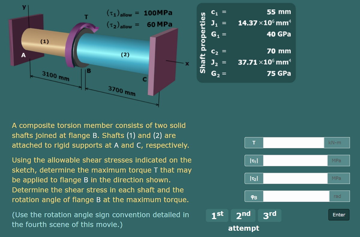
A composite torsion member consists of two solid
shafts joined at flange B. Shafts (1) and (2) are
kN-m
attached to rigid supports at A and C, respectively.
Using the allowable shear stresses indicated on the
MPа
sketch, determine the maximum torque T that may
be applied to flange B in the direction shown.
Determine the shear stress in each shaft and the
MPа
Фв
rad
rotation angle of flange B at the maximum torque.
2nd 3rd
(Use the rotation angle sign convention detailed in
the fourth scene of this movie.)
1st
Enter
attempt
I| || ||
I| || ||
Shaft properties
Expert Solution
This question has been solved!
Explore an expertly crafted, step-by-step solution for a thorough understanding of key concepts.

Step by step
Solved in 4 steps with 4 images

Knowledge Booster


Learn more about
Need a deep-dive on the concept behind this application? Look no further. Learn more about this topic, mechanical-engineering and related others by exploring similar questions and additional content below.Recommended textbooks for you
Mechanics of Materials (MindTap Course List)
Mechanical Engineering
ISBN:
9781337093347
Author:
Barry J. Goodno, James M. Gere
Publisher:
Cengage Learning
Mechanics of Materials (MindTap Course List)
Mechanical Engineering
ISBN:
9781337093347
Author:
Barry J. Goodno, James M. Gere
Publisher:
Cengage Learning