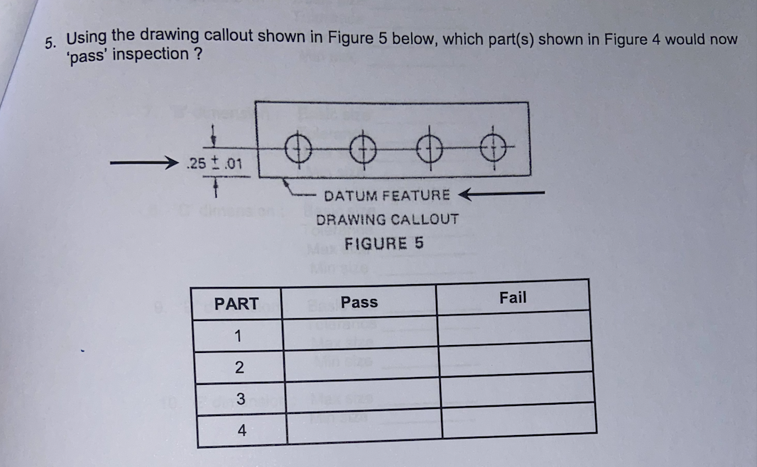
6 Using the drawing callout shown in Figure 5 below, which part(s) shown in Figure 4 would now 'pass' inspection ?


I am attaching both questions for 4 and 5 with the question in the image. thank you.
NOTE : So the last person answered this question WITHOUT refencing the answer for whether question 4 or 5 answeres were given, so i am asking for question 5(or the answer for the question that was NOT solved because it was not referenced.) These were the following answers given to me from the last person on bartleby who answered my question without referencing whether it was the answer for question 4 or 5.
1 pass
2 fail
3 fail
4 pass
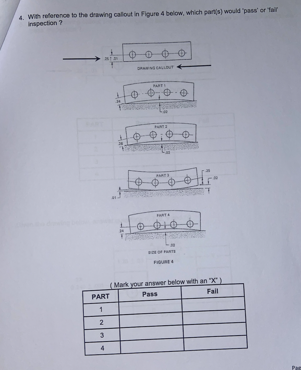
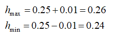
According to the given dimensional tolerance for the part, the maximum and minimum allowable deviation of the hole axis from the datum can be determined as,

Trending now
This is a popular solution!

Step by step
Solved in 5 steps with 5 images


