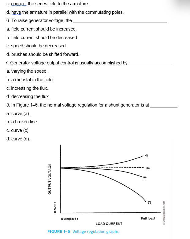
6. To raise generator voltage, the a. field current should be increased. b. field current should be decreased. c. speed should be decreased. d. brushes should be shifted forward. 7. Generator voltage output control is usually accomplished by a. varying the speed. b. a rheostat in the field. c. increasing the flux. d. decreasing the flux. 8. In Figure 1-6, the normal voltage regulation for a shunt generator is at a. curve (a). b. a broken line. c. curve (c). d. curve (d). OUTPUT VOLTAGE 0 Volts Ο 0 Amperes LOAD CURRENT FIGURE 1-6 Voltage regulation graphs. Full load Cengage Learning 2014


Synchronous Generator
In comparison to an asynchronous generator, it is a machine where the rotor speed is equal to the rotating magnetic field produced by the stator, i.e., mechanical speed is equal to the electrical speed, thus called synchronous, and not asynchronous.
Salient Pole Rotor
Salient pole rotor includes a large number of exposed poles mounted on a magnetic wheel. The construction of a bright pole is as shown in the image on the left. The proposed poles are made of metal laminations. The rotor winding is provided on these poles and is supported by pole shoes.
Select the correct answer for each of the following statements
Book Source: Electricity 3 | 10th Edition
ISBN-13:9781111646738 ISBN:1111646732 Authors:Jeffrey J. Keljik


Trending now
This is a popular solution!

Step by step
Solved in 2 steps


