
Physics for Scientists and Engineers: Foundations and Connections
1st Edition
ISBN:9781133939146
Author:Katz, Debora M.
Publisher:Katz, Debora M.
Chapter34: Maxwell’s Equations And Electromagnetic Waves
Section: Chapter Questions
Problem 18PQ

Related questions
Question
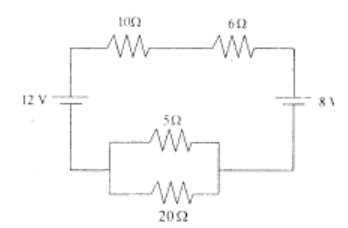
- Determine the
electric current that flows in circuit as shown in figure below.
Known :
Resistor 1 (R1) = 10 Ω
Resistor 2 (R2) = 6 Ω
Resistor 3 (R3) = 5 Ω
Resistor 4 (R4) = 20 Ω
Source of emf 1 (E1) = 8 Volt
Source of emf 2 (E2) = 12 Volt
Transcribed Image Text:W W-
12 V
512
202
Expert Solution
This question has been solved!
Explore an expertly crafted, step-by-step solution for a thorough understanding of key concepts.

Step by step
Solved in 3 steps

Knowledge Booster


Learn more about
Need a deep-dive on the concept behind this application? Look no further. Learn more about this topic, physics and related others by exploring similar questions and additional content below.Recommended textbooks for you
Physics for Scientists and Engineers: Foundations…
Physics
ISBN:
9781133939146
Author:
Katz, Debora M.
Publisher:
Cengage Learning
Physics for Scientists and Engineers: Foundations…
Physics
ISBN:
9781133939146
Author:
Katz, Debora M.
Publisher:
Cengage Learning