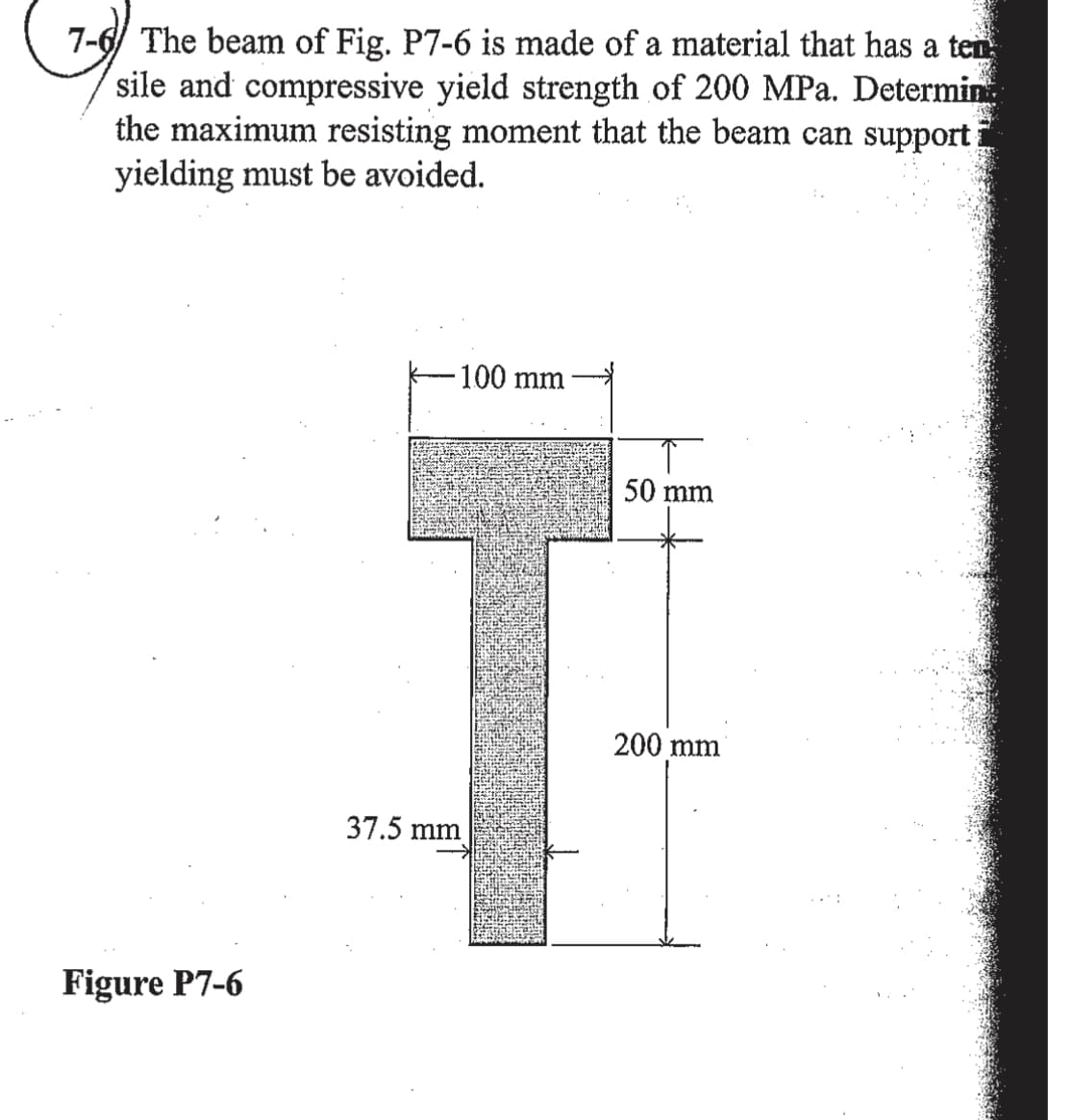
7-6 The beam of Fig. P7-6 is made of a material that has a ten sile and compressive yield strength of 200 MPa. Determin the maximum resisting moment that the beam can support yielding must be avoided. -100 mm 50 mm 200 mm 37.5 mm
Q: C8-49 A 500-lb load is supported by a roller on a beam as shown in Fig. Plot |Mmax, the maximum…
A: Free-body diagram of beam is given as, On using force equilibrium in vertical direction, On using…
Q: 5.108 The overhanging beam carries concentrated loads of magnitudes Pand 2P. If the bending working…
A:
Q: *RII-4. Determine the maximum bending stres in the handle of the cable cutter at section a-a. A…
A: For solution refer below images.
Q: 8-49 Using transformed sections, determine the maximum bending stresses in each of the two materials…
A:
Q: the bar element's linear shape, or interpolation ons are: N1= 1-x/L, and N2= x/L (where L is the ent…
A:
Q: Identify the correct reaction force value at A for a simply supported beam AB of length 5 m in the…
A:
Q: 9-13. A spring-supported pipe hanger consists of tuo speings which are originally unstretched and…
A: Calculating displacement on the spring, Calculating the displacement of the steel rod AB and CD,…
Q: 20. Determine the shear force at the right end of the uniform load. Use wo = 150 N/m, a = 1.3 m; and…
A:
Q: PROBLEM 2-30 The W250x22 cantilevered beam is made of A-36 steel and it is subjected to the loading…
A:
Q: 7-8 Find the rim tension and the bending stress in the rim of a flywheel, the section of which is…
A: The rim tension and bending stress in the rim of a flywheel with a rectangular shape, 39 cm broad…
Q: A leaf spring carries a central load of 3000 N. The leaf spring has to be made of 10 steel plates…
A:
Q: Determine the internal normal force, shear force, and bending moment at point C in the beam. 5 kN/m…
A:
Q: 17-3. Using Eq. 17-11 and taking advantage of symmetry, determine the flexural deflections at the…
A: Calculated deflection of beam at point load P by strain energy method.
Q: Determine the normal force, shear force, and moment at a section through point C. Take P = 8 kN B…
A: Given: force applied at the end of the section→P=8 kN
Q: A vertical shaft 25 mm diameter and 0.75 m long is mounted in long bearings and carries a pulley of…
A: Given data: The diameter of the shaft is d = 25 mm = 0.025 mThe length of the shaft is L = 0.75 mThe…
Q: P7-2. force resisted by the bolt. Include all necessary free-body diagrams. determine the largest…
A: Draw the free-body diagrams for both central panels respectively between 'A and B', and 'B and C'.…
Q: P9-5. The rigid beam supports the load of 60 kN Determine the displacement at 8. Take E = 60 GPa,…
A: Let's draw free body diagram of 'AB' and 'BC' Assuming 'A' and 'B' simple supports…
Q: 7-27 For the cantilever beam shown in Fig. P7-27, write equa- tipns for the shear force V, and the…
A: Given data: The load applied at end A is F = 1000 lb. The length of beam is L = 4 ft. Consider a…
Q: -1m-- 1m ---lm Problem 3 A rigid rectangular beam has a weight of 20 kN acting at its center of mass…
A: G is the midpoint of CD; Taking the upper part from section X---X' Moment about C = 0; ∑M(C)=0 FBD…
Q: The three-dimensional state of stress at ap given by 30 10 -10 [0] = 10 20 MN/m? %3D -10 20
A: Given: σ=3010-1010020-10200 MN/m2
Q: 6-125. The beam is made from three types of plastic that are identified and have the moduli of…
A: EPVC=450 KsiEE=160 KsiEB=800 KsiLoading is symmetric therefore;RA=RB=500 lb
Q: 20 kN 10 kN.m 4 m 2 m
A:
Q: 7-49*) Draw complete shear and bending moment diagrams for the beam shown in Fig. P7-49.
A:
Q: Consider a simple supported beam subjected to the load shown. The beam has a solid circular…
A:
Q: 29.11 KN /m -(x 4.5m A x Ma 2.12 m Ay ↑ 一 29.97 kN/m
A: Shear force at any section is found by the summation of all the shear force on either left or right…
Q: 9-18. A simply supported beam is subjected to a quadratic distributed load as shown in Fig. P9.18. y…
A:
Q: A cantilever beam 2.5 m long having T-section as shown in Fig. 9-15 carries two concentrated loads.…
A: Two focused loads are carried by a 2.5 m long cantilever beam with a T-section as shown in the…
Q: 120 mm 10 kN/m B 5 m Format TL GyabGSkin -j1-0630b/a) My It - , cos20 + Taysin2e. ut =*, tan20, -…
A: The maximum bending moment in a simply supported beam with uniformly distributed load - M=wL28 where…
Q: 5.41 The inverted T-beam supports three concentrated loads as shown in the fig- ure. Find the…
A: To Find : The maximum allowable value of P . Given: The bending stress is σt=3.5 ksiTension, σc=8…
Q: 1 Draw shear and moment diagram. Det. max. V and max. M 2. Draw loading and moment diagram given the…
A:
Q: Find A v, and theta, as assigned, at the center of the span due to the applied loads shown in the…
A: To calculate the deflection and slope at the lid-point of the beam, we will use the elastic equation…
Q: 5.118 The simply supported timber beam has a square cross section. Find the smallest allowable value…
A: For solution refer below images.
Q: P9-4. The rod is subjected to an extemal axial force of 800 N and a uniform distributed load of l100…
A: Given data: The axil force, Fa = 800 N. The uniformly distributed load, w = 100 N/m. Draw the…
Q: using the curved-beam theory thesPr.ny bending stresses are givenby Prove that Gb=K; (6Fir for 93…
A: given; bending stress (σb)=k.M.yIprove that (σb)=k.6F.ra3 dimension of square cross section=a
Q: Q 2: A cantilever beam has the profile shown so that it will provid sufficient clearances for large…
A: Given
Q: Identify the correct reaction force value at A for a simply supported beam AB of length 5 m in the…
A: Let us consider the reaction at A and B Let us draw the free body diagram F1=20N (Given) B=4N…
Q: 6-126 The wooden section of the beam is reinforced with two stedl plate as shown. II the beam is…
A:
Q: 31 A beam is loaded and supported as shown in Fig. P7-31. Using the coordinate axes shown, write…
A:
Q: thrust bearing journal bearing D A _B E – 4 ft - 4 ft 4 ft → 4 ft --4 ft 'SN Ibs FN Ibs
A: To find: The internal loadings at point E: Internal axial force at E is, NE = ? Internal shear force…
Q: Pu-250KN Pu-250KN draw shear force and bending moment diagram and With all details ofthe solution…
A: I have made both diagrams clearly and solved the question step by step with each point calculation.
Q: The bending moment diagram and cross-section for a beam are shown below. Use the elastic flexural…
A: Given: The maximum bending moment in compression from bending moment diagram, M = 40 kip.ft The…
Q: Wo -L/2– -L/2- Fig. P17-16
A: Deflection at B by Modified Castigliano's theorem.putting an imaginary force P at B.…
Q: 50 kN -10 kN/m 3 m 2 m 2 m 2 m Fig. 9.47 [Ans. Fg = 70.83, FE = 29.17, Mmax = 45 kN-m at B %3!
A:
Q: Helical spring with mean diameter (Dm-30mm) and manufactured from wire with diameter (d=3mm). if the…
A:
Q: Q4.36 critical section AA of a crane hook is considered, for purpose of analysis, to be trapezoidal…
A:
Q: The composite shaft, consisting of aluminum. copper. and steel sections, is subjected to the loading…
A: Given data: EAl=10×103 ksiEcu=18×103 ksiEst=29×103 ksiAAB=0.09 in2ABC=0.12 in2ACD=0.06 in2 Need to…
Q: A locomotive semi-elliptical laminated spring has an overall length of 1.3 m and sustains a load of…
A: Given data as per question length =1.3mload=78KNNumber of full leaves=2Number of graduated…
Q: FIG. P8.2, P8.60 3 m- -1 m- FIG. P8.3
A: As per given question Draw vertical reaction at point A and C Shear force at point B and bending…
Trending now
This is a popular solution!
Step by step
Solved in 3 steps with 3 images
- A sign of weight W is supported at its base by four bolls anchored in a concrete footing. Wind pressure P acts normal to the surface of the sign; the resultant of the uniform wind pressure is force fat the center of pressure (C.P). The wind force is assumed to create equal shear forces F/4 in the y direction at each boll (see figure parts a and c). The overturning effect of the wind force also causes an uplift force R at bolts A and C and a downward force (— R) al bolts B and D (see figure part b). The resulting effects of the wind and the associated ultimate stresses for each stress condition are normal stress in each boll (h — 60 ksi); shear through the base plate (th = 17 ksi); horizontal shear and bearing on each bolt ( tfur = 25 ksi and cr^ = 75 ksi): and bearing on the bottom washer at B (or D) (abor = 50 ksi).A simple log bridge in a remote area consists of two parallel logs with planks across them (see figure). The logs arc Douglas fir with an average diameter 300 mm. A truck moves slowly across the bridge, which spans 2.5 m. Assume that the weight of the truck is equally distributed between the two logs. Because the wheelbase of the truck is greater than 2,5 m, only one set of wheels is on the bridge at a time. Thus, the wheel load on one log is equivalent to a concentrated load W acting at any position along the span. In addition, the weight of one log and the planks it supports is equivalent to a uniform load of 850 N/m acting on the log. Determine the maxi mum permissible wheel load W based upon (a) an allowable bending stress of 7.0 MPa and (b) an allowable shear stress of 0.75 MPa.The shear stresses t in a rectangular beam arc given by Eq. (5-43): in which Fis the shear force, / is the moment of inertia of the cross-sectional area, /lis the height of the beam, and i] is the distance from the neutral axis to the point where the shear stress is being determined (Fig. 5-32). By integrating over the cross-sectional area, show that the resultant of the shear stresses is equal to the shear force V.
- 3. A 3-meter-long beam is used to support a heavy object. The object has a uniform distributed load of 6 kN/m on the entire beam. The Young’s modulus and moment of inertia of the beam are 200 GPa and 5×105 mm4, respectively. The beam is supported at three positions as shown below. (a) Label the element and node numbers (either on the figure or with a new simple sketch). (b) Determine the slopes at the three support positions of the beam.ts=600g, TL=18pounds , angle=780degree ,can you please find the solution and free body diagram9-18 A rectangular vertical member fixed at the base is loaded as shown in the figure. Find the location for a gage on member face AB such that no longitudinal strain would occur due to the application of force P = 6 kN. Does the answer depend on the magnitude of force P? Assume elastic behavior. All dimensions are given in mm.
- For the simply supported beam carrying the concentrated load P = 268 N at its midspan, determine the magnitude of the maximum displacement (in mm) if d = 1.51 m, E = 11.77 GPa , and I =1679930mm4. NOTE: PLEASE ANSWER IT CORRECTLY. IF YOU ARE NOT SURE ABOUT THE ANSWER, PLEASE SKIP THE QUESTIONPLEASE BOX THE FINAL ANSWER(S)THANK YOU! image below for reference17-37. An inclined steel bar 2 m long, having a cros section of 4000 mm² and an I of 8.53 x 10 mm, is supported as shown in the figure. The inclined steel hanger DB has a cross section of 600 mm". Determine the downward deflection of point C due to the application of the vertical force of (2.SQRT(2)) kN. Let E = 200 GPa.Prob # 3. Find the torsional deflection of a solid steel shaft 100 mm in diameter and 130 mm long subjected to twisting moment of 3 x 10⁶ N-mm. The torsional modulus of elasticity is 80,000 N/mm2. a. 122 deg b. 285 deg c. 0.234 deg d. 0.543 deg
- For the following structure, represent Mohr's Circle at point K of the structure and pointSection P, demonstrating the following steps:a) Effort diagram;b) Calculation of the geometric properties of the section; θ= 10thq=61kN/mV= 51kNN=48kNh1 = 221 mmb1=221 mmh2=t=21 mThe beam safely supports shear forces and bending moments of 2kN and 6.5 kN-m respectively. Based on this criterion, can it be safely subjected to the loads F = 1kN and C = 1.6 kN-m? Use the integration methodSolve the preceding problem using the fol low-data: W 8 × 21 section, L = 84 in., P = 4.5 kips, a = 22.5°.